Testing and Designing Part Features for Volume Production
One way to check the validity of your 3D printed parts is to use an add-in for your CAD software that provides manufacturability feedback.

If you are interested in volume production, one of the easiest, yet most commonly overlooked, steps in the design process is testing your part features. One way to check the validity of your parts is to use an add-in for your CAD software that provides manufacturability feedback. The integration of Xometry in SOLIDWORKS is an excellent resource for engineers and designers, providing instant feedback on the manufacturability of your parts.
However, additive manufacturing is often an iterative process. Features do not always print as-desired the first time, particularly in FDM. Often small features like snap fits or interlocking geometries need to be iterated multiple times in order to yield a suitable part. For features on a larger part, you can choose to build only the section of the part that contains the feature. You can also test multiple features per part (This is often useful when determining an offset for an irregular shaped hole where a mating piece will fit). Below are some helpful tips and illustrations for designing fixtures for your 3D printed parts correctly to help minimize iterations and errors.
For even more information, head to our resources page to see our 3D printing design guides.
Ribs and Fillets
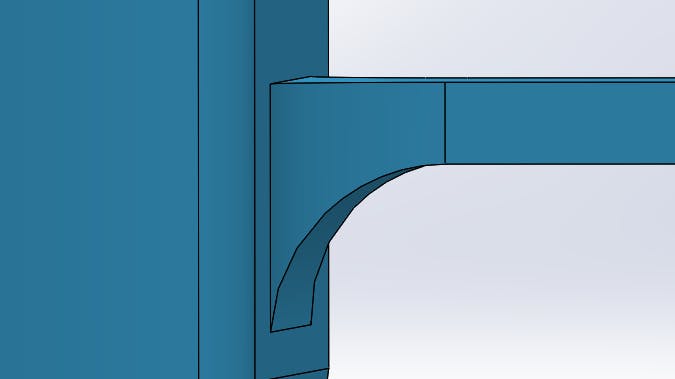
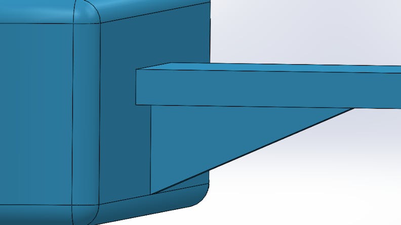
Ribs and fillets are a great way to increase structural support in your part. But designing them too thin or improperly leaves them susceptible to breaking. In all additive processes, it is important to make fillets as large as possible in order to increase the surface area involved in a connection.
Fillet feature
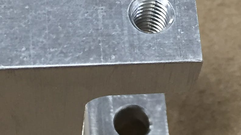
An example of a tapped hole
Pockets and Cavities
Parts with confined cavities or pockets make it impossible to remove material during post-processing on SLS and metal binder jetting.
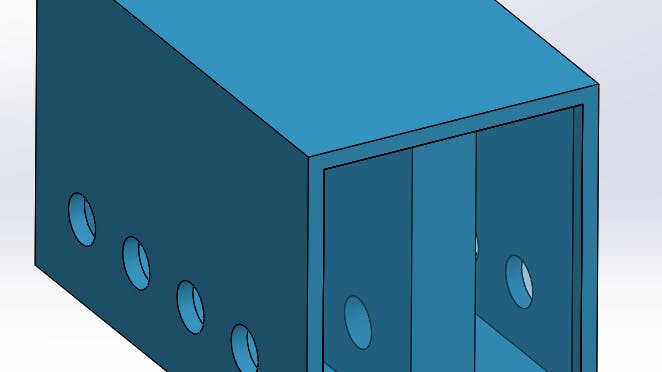
For SLS make sure to design relief holes to allow un-sintered material to exit the part when completed. Xometry recommends 2 or more relief holes of 0.500” (12.7 mm) in diameter if possible. Building these holes within line-of-site allows for much more successful cleaning.
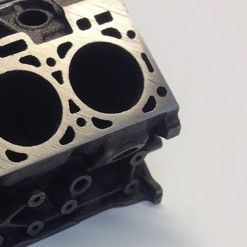
And for metal binder jetting, the number of exit holes depends on the height of bosses and the size of enclosures. Xometry recommends an exit hole of at least 0.1” (2.54mm) in diameter and every 0.5” (12mm) to guarantee sufficient cleaning.
Cavities with relief holes
SLS Pins
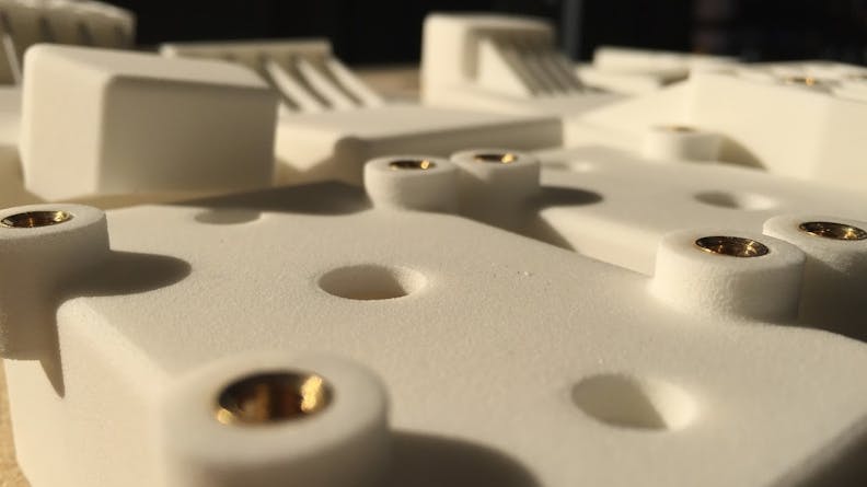
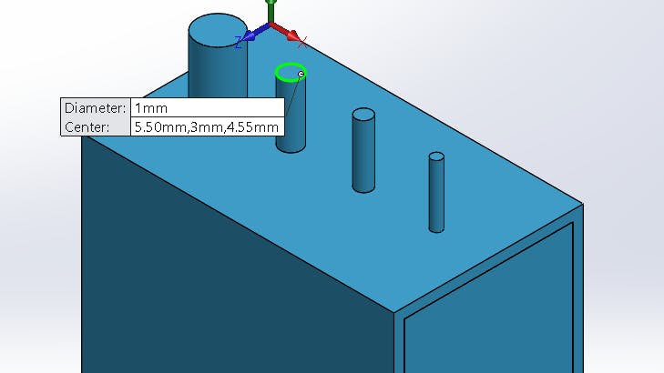
The main difficulty when designing pins for SLS is the risk of small pins breaking off during post-processing. The taller the pin, the greater the risk of breaking; increasing its diameter will give a tall pin more strength. Alternatively, part performance can be improved by creating a hole where a pin would be and inserting a separate metal pin during post-processing.
Pins with an expanding diameters

