3 Mistakes to Avoid When Working with Legacy Drawings
Often, the quality of PDF drawings can be the biggest barrier to successful projects because they were scanned or copied from a physical paper print. Here are some mistakes to avoid when sending a drawing to a manufacturer.

Manufacturing from a 2D drawing or print is still heavily used to serve established companies. Many legacy parts do not have updated 3D models and digitally-generated drawings. This is often because when they were first produced, CAD did not exist. For defense, automotive, aerospace, and industrial sectors, this can mean that the only reference that can be used to get a replacement part is the original print. Typically printed on paper or vellum, these prints are scanned or copied to create a digital file. But when it comes to communicating with your manufacturer, those copies can be a mixed bag.
Xometry's application engineers have seen a widespread need for quotes on legacy parts with only a print and capable manufacturers who can fabricate and finish the parts into reality. These parts are often machined components, sheet metal fabrications, or assemblies. However, older drawings and hand sketches can sometimes be tough to interpret because of low-quality originals, degraded resolution from repeated scans, and incomplete technical data. Below are a few examples of three common mistakes to avoid when working with scanned drawings.
Mistake #1: Drawings that are Plain Illegible
When an old drawing finally gets scanned into a digital file, there is no guarantee that the drawing used is actually the original. It could be, itself, a copy or from a series of copies. Each time a copy is made, there is a chance that details may be lost. By the time some older prints, like those originally made in the 1950s, ’60s, or ’70s, are digitally scanned, there may be so many artifacts in the print that it may take serious detective work to figure out what the notes or dimensions actually say. One of the first things manufacturers look for when reviewing 2D technical drawings is if there are any unreadable or ambiguous areas that require clarification.
Other examples of this mistake are when prints are half-scanned, cutting off critical information on edges such as a title block or notes callout. This is common for large blueprint drawings that may have been too big to be scanned in one go. Either way, the part may require some reverse engineering or calls to the original engineers to find a better copy or make a brand new version of the file. A general rule of thumb is that if you cannot read it, neither can the manufacturer.


A plain illegible drawing
Mistake #2: Providing an Assembly Drawing Without Part Details
Another challenge with legacy components is that they may actually be the upper-level assembly of several discrete mechanical components. Assembly drawings are typically built to define how each component relates to the other when assembled. This can include how many of each component, each component's unique name, how many of each part is needed, and possibly some minor distance or fit validation measurements. Unfortunately, that does not help the manufacturer if they are needed to make the sub-components of the assembly. Manufacturers require detailed mechanical drawings of each part to properly build the finished product.
One thing a buyer or engineer can check for when sourcing for assemblies is if each component is outlined on the drawing with technical specifications. This should be specifications like dimensions, material, finishes, and markings. Assembly drawings can have a front page bill of material sections that outline the components, quantity, and sometimes (if you’re lucky) following pages in the drawing with their supplemental manufacturing information.

A drawing with incomplete information for the assembly parts
Mistake #3: The Drawing is Incomplete
This third challenge marks a paradigm shift between older, 2D-drawing-only prints and newer, CAD-controlled drawings. In CAD-controlled drawings, the best practice is to provide the 3D CAD model and use the print for supplementary critical tolerances, threads, features, finishes, etc. The 3D CAD model is sufficient for the majority of the part’s geometry, while the supplemental drawing can provide select details that the 3D CAD does not. When providing a manufacturer with only a flat drawing, such as a PDF or even a hand sketch, the information must be complete. There should be a reference for every hole location, fillet, feature distance, thread, depth, etc. A fully defined drawing ensures that, if properly produced, the part will have no critical variation between manufacturing runs or individual manufacturers.
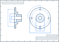
Incomplete information, like the missing thread callout in the image below, may not always be as obvious as a missing measurement. Sometimes it could be missing notes, like materials or finishing requirements. In legacy drawings, it may be a specification call out to an unreleased internal document. Manufacturers typically look at the part, then to the title block, then to the notes, and repeat to check if all information is available to successfully produce the project.

An incomplete drawing
Manufacturing-ready Drawings Checklist
When working with a legacy drawing, scan, or hand sketch, check for the following before submitting to a manufacturer:
Title block information
- Part name, part number, and revision
- Unit scale (inch, millimeter, etc.)
- Title block tolerances (e.g. per ASME Y14.5-2009)
- Drawing perspective, e.g. 3rd angle projection
- Sheet page and number of pages (to check for missing pages)
Part-specific information
- Appropriate drawing views and dimensions for each feature
- Datums, GD&T, or critical tolerances as applicable
- Threads callouts with size, tolerance class, and depth
Numbered notes section
- Material and alloy grade or specification
- Coating or finishing notes and requirements
- Edge break requirements
- Other notes and flagged indicators on the drawing where they are relevant
Other
- Part name, part number, and revision
Summary
Ensuring drawings are legible, providing all drawings required for an assembly’s subcomponents, and ensuring all required part data is there will help manufacturers understand your project needs immediately and quickly return an accurate quote to you. If possible, create a 3D CAD file to accompany the drawing. Custom manufacturing has transitioned away from using 2D drawings as the sole source of information to make parts. An ever-increasing number of manufacturers rely on 3D CAD to generate the commands and toolpaths that CNC machines, 3D printers, and other equipment use to build parts.
Once you have a model and technical drawing ready for manufacturing, you can securely upload them to the Xometry Instant Quoting Engine® to get an instant quote on your next project!