Normal to Surface Cuts in Tube Manufacturing

Overview
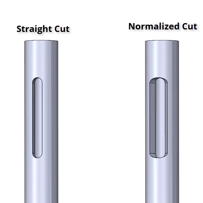
Though often unassuming, laser tube cutting projects can be quite complex with many cuts, such as miters and copes. Cuts are often modeled normal to the edge using standard extrude and cut features in CAD. However, the actual cut path for laser tube cutting is 90 degrees, or normal to the surface of the tube. This article helps you understand what a normal-to-surface cut is and what to expect when ordering laser tube cutting services.
Normal-to-Surface Cuts
A normal-to-surface cut is perpendicular to the outside surface of the tube. Normal-to-surface cuts have many aliases, including normalized cut, 90-degree cut, or true cope. Whatever their name, normal-to-surface cuts are the industry standard for laser tube cutting.
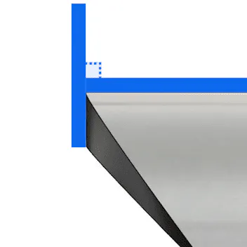
Quoted laser tube cutting projects will always assume the cuts in your model are normal to the surface. Normal-to-surface cuts can decrease lead times and price. This is because normalized cuts allow the laser head to remain at a 90-degree angle to the tube surface at all times during manufacturing, giving a consistent cut thickness on the tube regardless of the feature.
Normal-to-Edge and Other Cuts
While possible, performing normal-to-edge cuts would require a manual review for quoting and increase lead time and price. This is because the laser must have an additional axis to tilt and cut the tube at an angle, increasing the time to cut features on the tube. Other types of cuts, like post-machined cuts, would also require a manual review. Maintaining a 90-degree angle standard reduces cutting difficulty and excessive heat build-up caused by making sharp cuts in thick-walled tubing.
Differences Between CAD and a Normal Cut Surface
It's important to make sure your CAD models resemble your end part. CAD software, such as SolidWorks, likely won’t assume normal to surface cuts. Many SolidWorks weldment tools and other tube modeling workflows do not normalize surfaces automatically. It takes a few extra commands to normalize your tube cuts, but this practice can reduce manufacturing issues and confusion.
Designing Normalized Cuts
There are many ways to normalize your cuts in CAD. It’s a good idea to get familiar with different techniques, as the same technique won’t always work for different cuts. You can learn how to normalize different cuts in the following guides:
- Designing Normalized Coped Cuts on Round Tube
- Designing Normalized Mitered Cuts on Round Tube
- Designing Normalized Mitered Cuts on Rectangle Tube
Pro Tip: Wonder if a cut is normal to surface? Rotate your model and imagine if a laser could make every cut perpendicular to the surface of the tube. If not, that surface may look different when fabricated.
Image Gallery
 Normal to Edge Miter
 Laser Path Reference
 Normal to Surface Miter
 Normal to Edge Miter
 Laser Path Reference
 Normal to Surface Miter
 Normal to Edge Notch
 Laser Path Reference for Notch
 Normal to Surface Notched Cope
 Normal to Edge Cope
 Laser Path Reference
 Normal to Surface Cope
 Normal to Edge Holes
 Laser Path Reference
 Normal to Surface Holes
 Normal to Edge Holes
 Laser Path Reference
 Normal to Surface Holes
 Normal to Edge Miter
 Laser Path Reference
 Normal to Surface Miter
 Normal to Edge Miter
 Laser Path Reference
 Normal to Surface Miter
 Normal to Edge Holes
 Laser Path Reference
 Normal to Surface Holes
 Normal to Edge Holes
 Laser Path Reference
 Normal to Surface Holes
FAQ
Xometry's Tube and Fabrication Services
Laser Tube Cutting Services
High-quality tube laser cutting for metal rectangular, square, and round tubes | Free standard shipping on US and international orders | International prototype pricing includes tariffsTube Bending Services
Xometry offers precision tube bending services for round metal tube stock to meet your needs.Custom Online Weldment Services by Xometry
High-quality custom weldment services available for a variety of materials, manufacturing processes, finishes, and more.