Top 5 Design Tips for Nexa3D LSPc


We've compiled our top design tips for Nexa3D's LSPc® 3D printing process. Keep reading to learn more about the guidelines you need to keep in mind to succeed with LSPc® technology!


Xometry is excited to offer the Nexa3D LSPc® printing process as part of our expansive additive manufacturing menu within the Xometry Instant Quoting Engine®! As with any manufacturing process, it's vital to thoughtfully design your components with the unique aspects of the technology in mind to ensure the most successful outcome. That's why we've put together our top design tips so you can get a head start on 3D printing with LSPc®! In the sections below, we'll cover the following design-related topics:
- Holes
- Wall Thicknesses
- Threads
- Text Features
- Hollow and Cupped Geometry
Tip #1: Hole Diameters and Depths
LSPc® uses photo-cured resins, or photopolymers, to build parts from. Designers should consider factors such as surface tension and cure-through regarding holes. If a hole is too small, it may close shut due to cure-through. Likewise, holes that are too deep or do not have proper drainage may hold excess resin after printing which could solidify in place during the UV curing stage of post-processing. The minimum recommended hole size will vary depending on whether the hole is through and the material's transparency. The chart below can help guide you on how to size your holes accordingly.
Pro Tip: Avoid large hole aspect ratios and blind holes. Add venting to the bottom of blind holes whenever possible to help drain excess uncured resin during cleaning.
| Design Feature | Recommended | Achievable * |
|---|---|---|
Design Feature Blind Hole Depth | Recommended < 3x Hole Diameter | Achievable * < 8x Hole Diameter |
Design Feature Through Hole Length | Recommended < 8x Hole Diameter | Achievable * < 25x Hole Diameter |
Design Feature Vertical Hole Diameter | Recommended > 0.8mm | Achievable * > 0.3mm |
Design Feature Non-Vertical Hole Diameter | Recommended > 1mm (Opaque Resins) | Achievable * > 0.6mm |
* Achievable with special washing techniques which may incur additional lead-time.
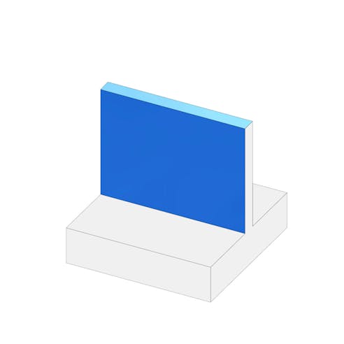
Tip #2: Wall Thicknesses
As with most manufacturing processes, thin walls that may break during printing or post-processing should be avoided. However, designers should also remember that excessively thick walls may retain high amounts of heat due to the exothermic reaction produced as the resin cures or even prevent complete curing. It's best practice to balance wall thicknesses so they are neither too thick nor too thin. Freestanding walls as thin as 0.5mm may be possible; however, the risk of failure is increased the closer to this thickness you get. Thicker parts or walls greater than 25mm in thickness are possible but may need to print slower to control heat and shrinkage.
Pro Tip: Keep walls between 1mm - 5mm thick and as uniform as possible. Support ribs spaced at a 25:1 ratio (i.e., a rib every 25mm for a 1mm thick wall) can help stiffen and strengthen walls.
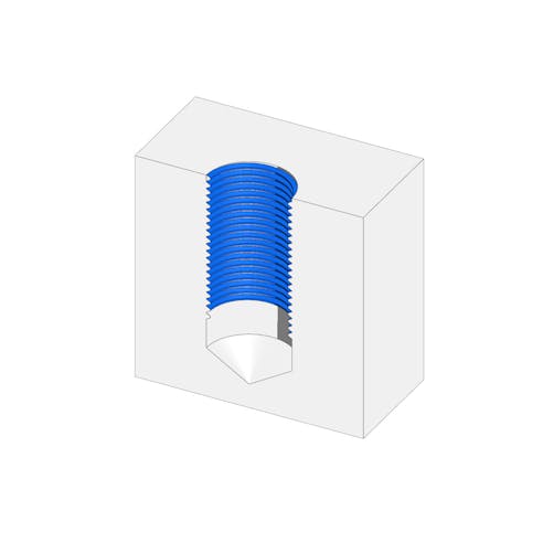
Tip #3: Threads
Cure-through, orientation, and support structures are considerations when designing threaded features in an LSPc® printed part. The technology works well with large thread forms, like those used with bottle caps. However, the finer pitch of smaller threads can become challenging.
We recommend following these guidelines when it comes to threads for this technology:
- Use larger threads whenever possible, such as M10x1.5 or 3/8-16 UN ; avoid going below M4x0.7 or #8-32 UN
- Printed threads resolve best when orientated perpendicular to the build platform
- For functional threads, chase them with a tap or die after curing; note that printed threads may experience wear with repeated fastening
- For smaller threads or when fastening using metal bolts and screws, use metallic inserts such as press-fit or heat-set inserts

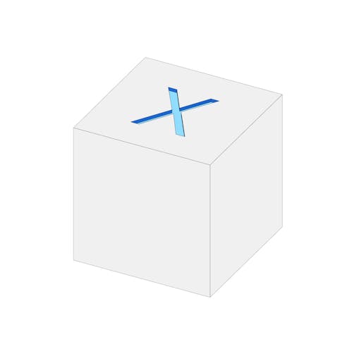
Tip #4: Text Features
Text can be embossed so it protrudes from a surface or engraved so it sits below the surface. In either case, character height and line width should be primary factors to consider in your design. Line width refers to the thickness or width of the lines that form characters, where character height is the total vertical size of a character from top to bottom. If either of these aspects is too fine, they may not correctly resolve, rendering the text illegible. Refer to the guidelines in the table below to ensure your text features are designed well for the process.
Pro Tip: Avoid using calligraphic or serif fonts since they often have narrow elements.
| Text Parameter | Recommendation | Achievable * |
|---|---|---|
Text Parameter Character Height | Recommendation > 4mm | Achievable * > 2.5mm |
Text Parameter Emboss Height or Engrave Depth | Recommendation > 0.5mm, or equal to line width | Achievable * > 0.25mm |
Text Parameter Line Width | Recommendation > 0.4mm | Achievable * > 0.25mm |
* Achievable based on build orientation, typeface and other printing variables.
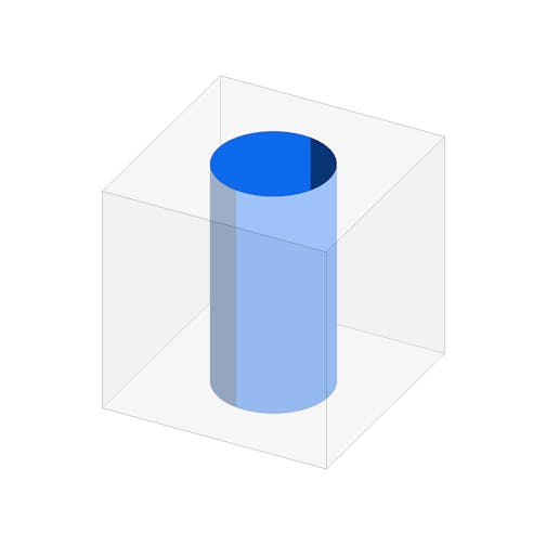
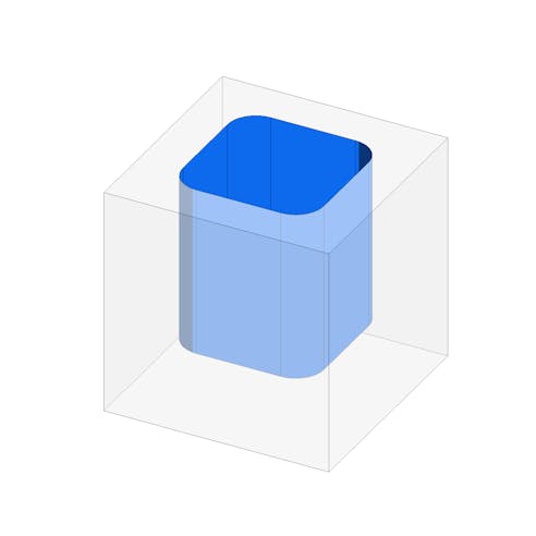
Tip #5: Hollow and Cupped Geometry
It is important to consider how your part geometry may interact with the unused resin surrounding the part as it is printed. For instance, if your part has a hollow section, the resin could become trapped inside the piece, leading to defects and problems during curing. Cup-shaped features that print open to the vat can induce vacuum forces that pull up resin and pressurize it when the z-axis raises and lowers as part of the printing process, leading to print problems. Strategically designed drainage holes can help mitigate these issues.
Follow the guidelines below for best practices for adding drain holes to your design:
- Use multiple drain holes at least 3mm in size
- If only one drain hole is possible, make it at least 5mm in size
- Place drain holes in corners or in areas where fluid would naturally flow towards
- Add vent holes to the base of cupped features to avoid suction forces; make their diameters 10% of the enclosed volume's span to ensure they are sized accordingly

Disclaimer
The content appearing on this webpage is for informational purposes only. Xometry makes no representation or warranty of any kind, be it expressed or implied, as to the accuracy, completeness, or validity of the information. Any performance parameters, geometric tolerances, specific design features, quality and types of materials, or processes should not be inferred to represent what will be delivered by third-party suppliers or manufacturers through Xometry’s network. Buyers seeking quotes for parts are responsible for defining the specific requirements for those parts. Please refer to our terms and conditions for more information.