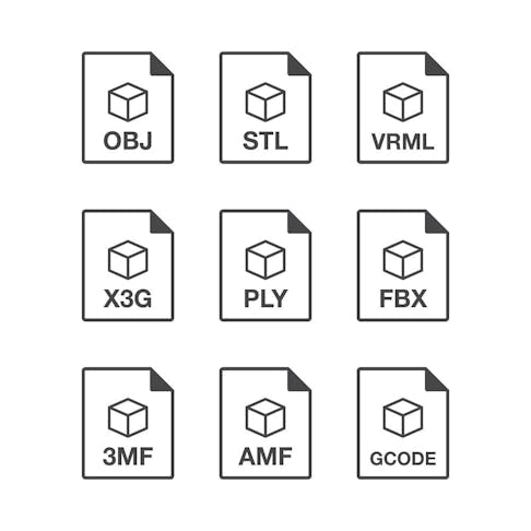
A 3D printer is a device that turns digital 3D models into 3-dimensional objects using 3D printing files. While there are several 3D printing file formats, they all have the same function—turning raw materials into solid objects. This article will discuss the most common 3D printing file types and explain what 3D printing file types are and how to make them.
1. FBX
FBX is an interchange format used for 3D geometry and animations. Various programs are compatible with FBX files, mostly those used in Augmented or Virtual Reality (AR/VR). Kaydara developed the FBX format for motion capture devices which aimed to store complete animation sequences. FBX files present difficulties in most slicer software—the format is not generally supported, so it’s necessary to convert it to a better-supported file for slicer compatibility.
2. OBJ
The OBJ file format originated from Wavefront Technologies for their Advanced Visualizer software. It is a common format for export and can be opened by most 3D design packages. OBJ is the preferred file type in colored 3D printing machines. The 3D data entails high-quality geometry, texture information, and full color. Virtually all slicers accept OBJ files as input.
3. STL
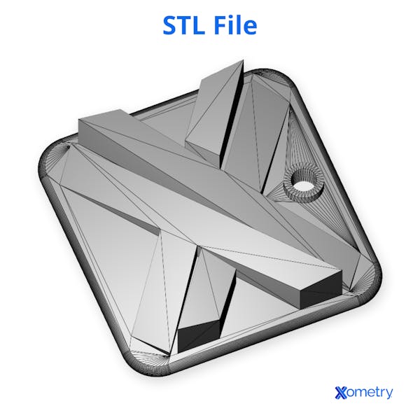
The STL file format is a widely used 3D printing file type. It is the input data for 3D slicer software. STL is derived from the name STereoLithography, which is the 3D printing process developed by Chuck Hull while working at 3D Systems in the 1980s. STL files contain simply the surface geometry of a virtual 3D object, with no other properties. The STL file format is universally supported by 3D CAD software.

4. 3MF
The 3MF format is a 3D XML-based system developed directly for additive manufacturing. It contains definitions for colors, materials, and precise shapes that are not present in STL files. Autodesk®, Dassault, Netfabb®, Microsoft®, SLM, HP®, Shapeways, and others are members of the 3MF Consortium that supports the 3MF format.
5. PLY
The PLY (Polygon File Format or Stanford Triangle Format) was initially developed to capture the shape and color data output from 3D scanners. PLY is similar to STL, but more attributes can be integrated such as: color/transparency, texture information, and scan data confidence values.
The PLY format was developed in the 1990s by Greg Turk and Marc Levoy, at the Stanford Graphics Lab. The PLY file format is not accepted by all slicers.
6. G-Code
G-code (.G or .GCO file extensions) files are the core instruction set for almost all CAM (computer-aided manufacturing) equipment and the operational language for most 3D printers.
G-code is the format of output from slicer software that converts CAD and VR objects into movement instructions that a 3D printer can interpret. M-code additionally allows slicer software to insert instructions that G-code does not contain and which are required in the operation of most 3D printers.
7. X3G
The X3G file format is a native format of MakerBot’s PRINT software and therefore not common in the additive manufacturing sector. PRINT and MAKERBOT software are used for slicing, editing, and build-table preparation of X3G models. It was released in 2012 with the Replicator Makerbot 2.
8. AMF
The Additive Manufacturing File (AMF) format was first introduced in 2011 as the ASTM format for 3D printing. AMF includes support for various properties in addition to surface geometry: color, material, duplicates, and orientation, the last two of which help in laying out build tables.
AMF sought to answer the shortcomings of STL by reducing the tendency to introduce disjoints and “leaks”. It also added support for full color, material, and build orientation.
9. VRML
VRML (Virtual Reality Modeling Language) is a common format for representing VR environments and objects. It became a de-facto standard in the environment and character design for gaming. VRML was launched in 1994 at the first World Wide Web conference by Mark Pesce and Tony Parisi.
VRML is a text format that includes vertices and edges of 3D polygons and also includes color, UV-mapped textures, reflectivity, and transparency. VRML is widely compatible with slicer software.

| 3D Printing Workflow | 3D Printing Files Used/ Generated | Description |
|---|---|---|
3D Printing Workflow Modeling | 3D Printing Files Used/ Generated Blender (.blend) SolidWorks (.sldprt) Step (.stp) etc. | Description 3D files in either native proprietary formats or general communications formats |
3D Printing Workflow Slicing | 3D Printing Files Used/ Generated .stl, .obj, .vrml, etc. | Description Either output files “save as” from design packages or outputs from 3D file conversion packages/online services |
3D Printing Workflow Printer files | 3D Printing Files Used/ Generated .cnc, .ngc, .gcode, .tap | Description Various formats required by machines from different manufacturers |
How To Make 3D Printing Files
- Acquire or develop a 3D model of an item you want to print. Make sure it has wall thicknesses that are suited to the printing process. Check if it has no disjoints or faults that might cause the slicing to fail. Additionally, review if the size of the object is suited to the printer you are using.
- Use the design software or a file converter with the right capabilities, to create one of the common file formats accepted by the slicer you intend to use. Commonly used communication formats to upload to slicer software are STL, OBJ, and VRML. Not all slicers can access all file types. Ensure that the resolution of the generated communication file is appropriate to the resolution of the printer and the complexity of the part you're printing.
- Upload this communication file to the slicer software you’re intending to use. Perform the slicing operation, making sure that settings such as scale, orientation, and slice thickness have been set appropriately.
- Upload the resulting sliced file as a machine instruction file—generally in one of the G-code formats—via Wi-Fi, USB, and SD Card.
- Print the part by setting the printer to complete the task, according to the uploaded G-code file.
Summary
Xometry provides a wide range of manufacturing capabilities including online 3D printing services, CNC machining, injection molding, laser cutting, and sheet metal fabrication. Get your instant quote today by uploading your files - we take a wide range of file types including some of those mentioned above.
Copyright and Trademark Notices
- Autodesk® is a trademark of Autodesk, Inc., and/or its subsidiaries and/or affiliates, in the United States.
- Windows® is a registered trademark of the Microsoft Corporation.
- HP® is a registered trademark of Hewlett-Packard Development Company, L.P.
- SolidWorks® is a registered trademark of Dassault Systèmes SolidWorks Corp.
Disclaimer
The content appearing on this webpage is for informational purposes only. Xometry makes no representation or warranty of any kind, be it expressed or implied, as to the accuracy, completeness, or validity of the information. Any performance parameters, geometric tolerances, specific design features, quality and types of materials, or processes should not be inferred to represent what will be delivered by third-party suppliers or manufacturers through Xometry’s network. Buyers seeking quotes for parts are responsible for defining the specific requirements for those parts. Please refer to our terms and conditions for more information.

