When you’re designing joining parts, the smaller details are just as important as the larger portions. Something as minuscule as an edge is a big determining factor in how smoothly two parts fit together or move off one another. That’s especially true for edge styles, like fillet and chamfer, which each bring their own benefits and greatly improve the joining and movement of two or more parts.
Edges like these provide two important features — an easier joining experience and reduced stress on certain areas of a part. A chamfer is helpful when you need to buffer the sharp change in direction, as it’s cut into an angled slope. Alternatively, a fillet is most useful if you need a smooth, curved edge to join two surfaces together, and it’s important for reducing the stress concentration that shows up in corners of a part or mating parts that are joined together, whether you’re machining small batches of products or rapid machining large quantities of mating components. Below, we explore specific details about how a fillet and chamfer work and when you’d use each style.
What is a Fillet?
Visually, a fillet edge is a smooth curve that waterfalls from the top of a part to the side. Engineers and designers can create this rounded style of edge for the interior or exterior of a part, and it’s handy in reducing pressure on tools or components that bear heavy loads. This type of edge is a popular solution when you’re casting, machining, molding, and 3D printing objects because the smooth design makes it easier for parts to slide around in comparison to leaving sharp edges on an object.
The two most common ways of crafting a fillet edge is through machining a radial tool path or 3D printing one. The first involves cutting a path between two surfaces on your object with machining tools, whereas the second gets designing through a software program and is set to create this type of surface during the 3D printing process.
Purpose and Design of a Fillet
When there is a change of direction or sections on a part, a fillet edge helps reduce the stress that comes with this switch. Its smooth, rounded edge creates less friction and takes a load off certain areas. This in turn means your parts won’t fatigue as quickly and it raises their load-bearing capacity. When it comes to reducing this stress, you’ll likely rely on a fillet edge over a chamfer for this purpose.
A fillet edge provides a little more than just function — it also helps boost the aesthetics of a part, since its edges are softer and rounded. The appearance of this edge on a part looks concave and rounded on interior surfaces, and unsurprisingly, convex and rounded on exterior corners. A fillet makes for a finish that looks seamless from all angles. However, one thing to bear in mind is that fillets can increase manufacturing time for subtractive processes, such as CNC machining, so incorporating them into your design simply for aesthetics may come at a higher cost.
You may find that a beveled edge reminds you of a fillet edge, but the two are not the same. A fillet is rounded, whereas a bevel is a diagonal cut. The latter is usually used when you need to weld or permanently seal two parts together for a strong joint.
What Is a Chamfer?
Another edge style to know is a chamfer. Its design features an angle or slope between two surfaces of a part that’s flat, as opposed to the fillet edge’s rounded surface. It’s also one option for improving the movement and joining of two or several parts. However, you probably wouldn’t choose a chamfer edge over a fillet style when it comes to reducing high levels of stress. Instead, they’re a great choice for assembling mating parts, especially at a 45-degree angle — though you can really customize them for any angle of your choosing.
Chamfers can be machined, like fillets, and they can be cut by hand. You can also design them in CAD programs, which makes it easier for certain machines or 3D printers to produce when it has already been programmed into the design. You’ll find they’re simpler to cut, too, because there isn’t a radius involved, like with a fillet. This fact also makes them a bit more economical to produce than fillets, so if you're simply looking to break a sharp edge, you may want to consider chamfers.
Purpose and Design of a Chamfer
Like a fillet, a chamfer edge also helps buffer the original sharp edges of a part, making assembly easier for mating components. You can choose from a variety of sizes and angles and lean on a single chamfer tool, countersink, or spot drill to make it.
You’ll notice a chamfer looks like a ramp or slanted surface and it will connect the top of a part to another side. When learning about the look and style of a chamfer, you might also think of a tapered edge, but there is a difference. A tapered edge is a gradual reduction in a specific dimension over the length of an object, whereas a chamfer is an edge style that’s only applied between two surfaces of a part.
Main Differences Between Edge Styles
Now that you understand what both a fillet and chamfer look like and how they’re used, let’s break down their three main differences.
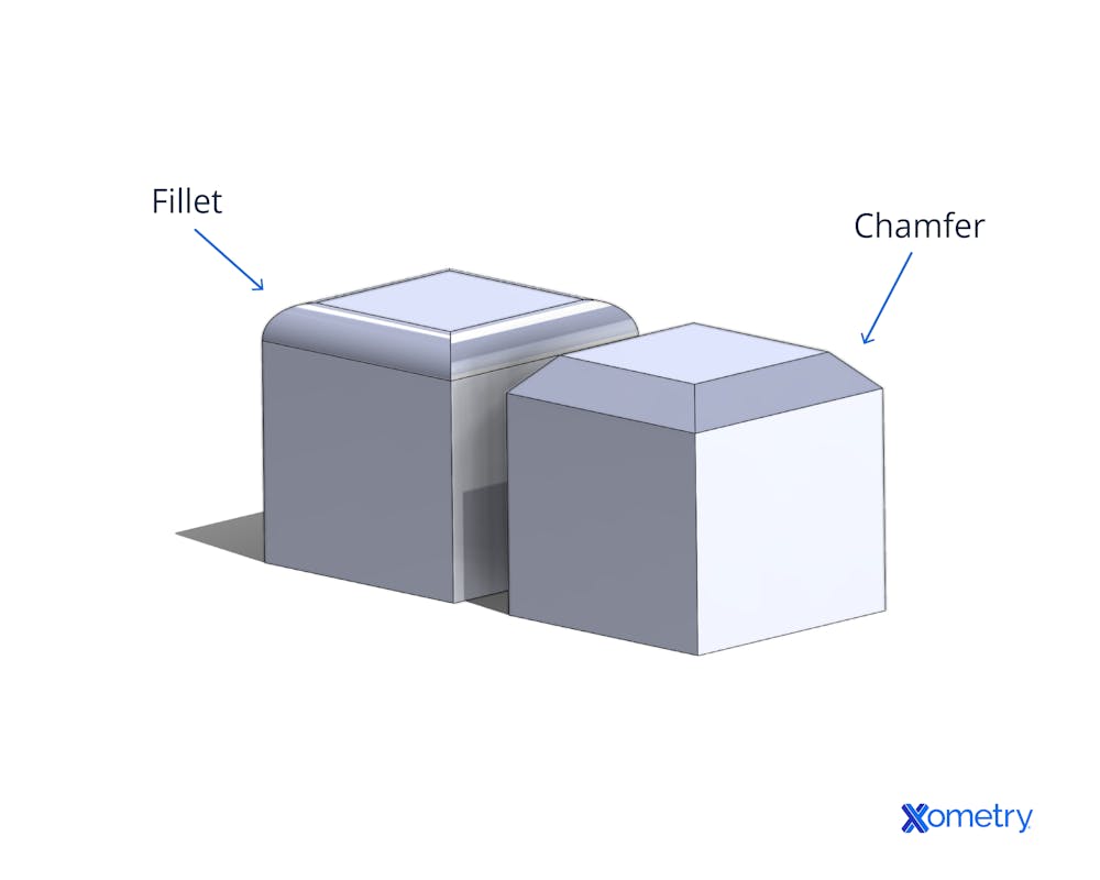
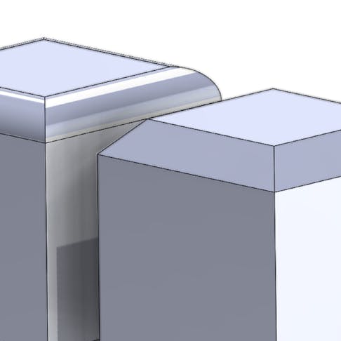
- Their visual appearance: A fillet edge is smooth and rounded, whereas you’ll see that a chamfer edge is angled, but they both connect two surfaces together.
- Their purposes: While both are made to ease up on sharp edges, a fillet edge is most helpful in reducing stress on parts that bear heavy loads, whereas a chamfer edge is ideal for joining mating parts.
- Their costs: A fillet edge is more expensive to manufacture because it involves cutting a radius and rounded edge, whereas a chamfer is a straight, angled edge.
The image below will give you an idea of how they compare visually and shows a sketch of two cubes, one with a fillet edge on the left and the other on the right with chamfered edges.

When to Use Each Type
You’ve learned that both fillet and chamfer edges have their own style and benefits, but let’s go more in-depth about situations when you’d want to select one or the other:
Instances in which you’d want to use a fillet edge include:
- Parts that will bear heavy loads: Fillet edges are best when it comes to parts that will be under pressure or carry heavy loads as they reduce stress — something that a chamfer doesn’t do as well.
- Parts will be presented or seen: A fillet edge provides an aesthetically pleasing finish, therefore if you’ll be showing a specific part or it will be on display, this could be a good reason to settle on this edge style.
- Benefits outweigh the cost: Fillet edges are more expensive to create, but if you find after some analysis that your parts require the benefits only a fillet edge can provide, it’s better to opt for this edge type.
Alternatively, the situations in which you’d want to use a chamfer edge include:
- Heavy loads won’t be involved: Unlike a fillet, chamfer edges aren’t well-equipped to handle heavy loads, so it’s best to understand how much weight or pressure you’ll expose the parts to.
- Mating parts are involved: To get the smoothest connection and movement between two mating parts, chamfer edges are the way to go, whether it’s for a pin, bolt, drive screw, or something completely different.
- Cost efficiency is important: When you compare these two edges, you’ll find that chamfered edges are cheaper to make than fillets since the former can be machined with simple tools in one motion rather than requiring more specialized tools or ones that require multiple sweeps to shape out curves. If a fillet’s benefits aren’t necessary, a chamfer will be more cost-efficient.
Knowing about these two styles of edges will make it easier to choose the right finish when it comes to combining parts of tools and machinery. Both fillet and chamfer edges offer unique purposes, it’s just a matter of considering what will serve the final product best in the end.
How Xometry Can Help
Whether you decide to use fillets, chamfers, or a combination of both in your part designs, Xometry can handle either with ease. As we mentioned in the sections above, cost can be a consideration between the two. With the Xometry Instant Quoting Engine® you can easily compare the costs of both edge conditions. Try quoting a machined part with chamfered edges, and then do the same for a version with fillets. The pricing and lead time differences will be revealed within seconds, allowing you to make the most informed decision.
Disclaimer
The content appearing on this webpage is for informational purposes only. Xometry makes no representation or warranty of any kind, be it expressed or implied, as to the accuracy, completeness, or validity of the information. Any performance parameters, geometric tolerances, specific design features, quality and types of materials, or processes should not be inferred to represent what will be delivered by third-party suppliers or manufacturers through Xometry’s network. Buyers seeking quotes for parts are responsible for defining the specific requirements for those parts. Please refer to our terms and conditions for more information.


