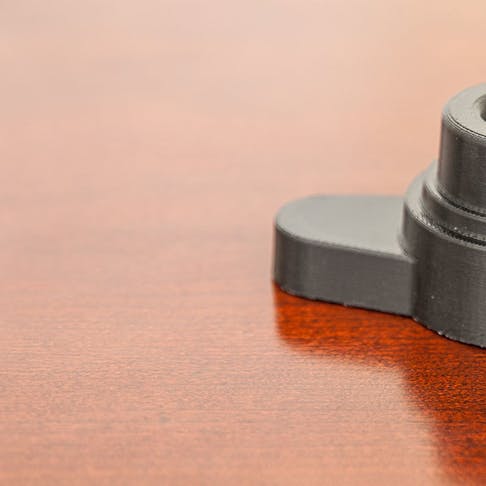
Fused Deposition Modeling (FDM) is an additive manufacturing process in which a machine precisely extrudes melted plastic filament to create a part. The filament is extruded out of a heated end, laying down in a zig-zag pattern to create the shape of the part from the bottom to the top. FDM technology can be used for rapid prototyping and is widely known for its speed, accuracy, and competitive cost. Parts are very rigid, especially compared to selective laser sintering (SLS), which makes them a great fit for projects with a rigidity requirement.
Our FDM Mini-Guide provides information on FDM's benefits, tolerances, and specific design features.
Real Engineering Thermoplastics
The availability of a broad range of engineering thermoplastics gives FDM a distinct advantage over other 3D printing technologies.
In addition to its vast material selection, FDM offers a wide range of color options.
- White
- Light Gray
- Gray
- Dark Gray
- Black
- Yellow
- Orange
- Red
- Green
- Blue
- Dark Blue
- Ivory
- Natural
- Translucent Natural
- Translucent Amber
- Translucent Red
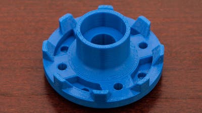
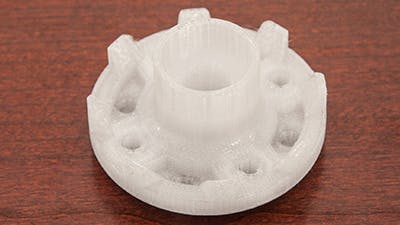
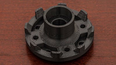
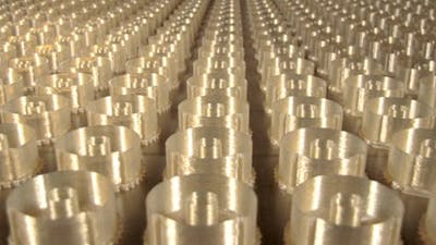
ABS: ABS is a strong and stable production-grade thermoplastic available in a wide range of colors and material properties.
Other Benefits
Complex Geometries
The freedom to design and manufacture complex geometries and intricate interior structures is one of the great promises of additive manufacturing. 3D printing technologies allow you to create parts impossible to manufacture any other way. Think outside the box!
Accuracy of FDM 3D Printing
Xometry’s FDM service allows you to produce parts with a consistently tight tolerance of +/-0.005″.
Large Build Volume
Xometry’s FDM solution offers large build volumes up to 36″ x 24″ x 36″.
Design Tip 1: Wall Thickness
3D printers produce parts by successively layering material. Wall thickness is limited by the filament size, and features thinner than twice the filament’s thickness usually do not print successfully.
Features with only one layer of filament are weak and inaccurate. For supporting structures, walls need to be at least 0.047” – 0.06” (1.2 – 1.5 mm) thick for best results by allowing filament to fill between layers.
Walls without closed profiles such as lines are also less resolved compared to those such as circular and closed loops. As a result, thinner, more circular walls are closer to design intent than those with straight walls.
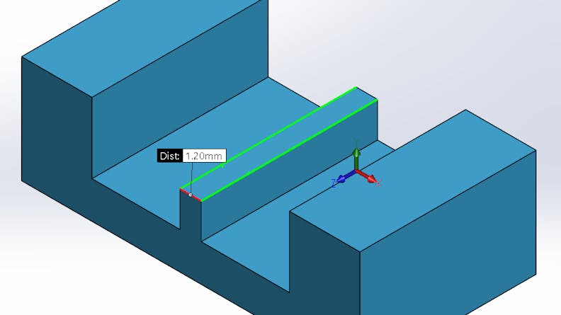
Recommended wall thickness is at least 0.047” – 0.06” (1.2 – 1.5 mm) thick for supporting walls
Design Tip 2: Orientation
Orienting parts in FDM has an enormous impact on its overall strength and appearance, especially for fine and concentric features. Concentric features resolve best when layers print parallel to the XY-axis. Many fine features (e.g. tabs) are stronger when printed parallel to the XY-axis as well.
Designing a part so that fragile and concentric features grow in the same direction will help determine the best orientation for a part to print.
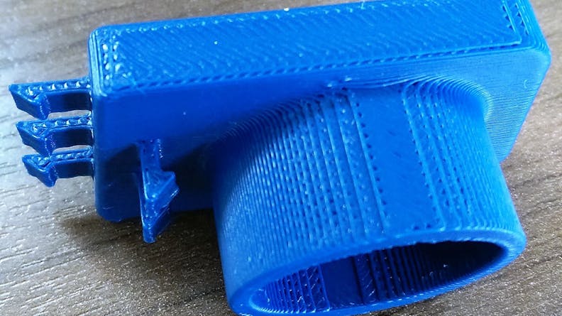
Orientation of the part matters
Design Tip 3: Holes
Xometry recommends that holes for FDM be designed with a diameter greater than 0.04” (1mm) to retain a circular shape. Orientation of holes is very important and resolution tends to be best when printed parallel to the xy-axis. This is because holes are outlined with concentric circles of filament versus staggered stops between layers. To increase the accuracy of through holes, Xometry may drill out holes during post-processing.
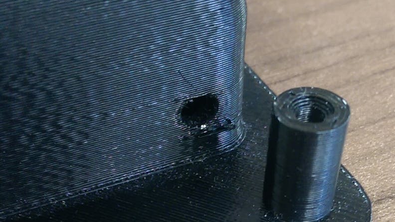
Holes in FDM parts
Design Tip 4: Text and Small Details
Text and small details are very difficult to print in FDM because many small features do not register in the printing process when they are below certain tolerances such as the filament’s thickness. Recommended thickness that protruding text must maintain is at least 0.04” (1mm) to register properly. Text must also have a height of at least 0.04” (1mm), but 0.047” – 0.06” (1.2 – 1.5 mm) is recommended to be legible and avoid unexpected errors, which will allow multiple layers of filament to stack on top of each other and reduce the risk of breakage. Cut-out text must also hold these tolerances to resolve properly. Be sure to use regular or larger text fonts, but stay away from more condensed and smaller fonts. All text must also be oriented parallel to the xy-plane for best results, because it will allow multiple layers to stack cleanly and avoid “squished” characters and details.
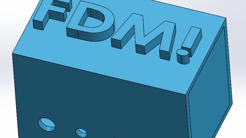
Text on an FDM CAD file
Design Tip 5: Tabs
Tabs are very susceptible to breaking in FDM, especially for larger parts. The first thing to do would be to increase the size of the tab as large as possible (size depends on the application and size of the overall part).
Orienting tabs parallel to the xy-plane will also increase the strength of the tab and reduce the risk of breakage. Integrating a replaceable tab design is another great way to use tabs in FDM, so that tabs may be printed separately in the best orientation then inserted Tab orientation post-processing.
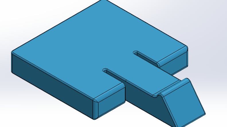
Tabs on an FDM CAD file
Design Tip 6: Ribs
Another great alternative to fillets for increasing the strength of support structures is by adding ribs. This is because ribs distribute the force applied to a structure to a greater surface area. It is important to follow tolerances outlined in the wall thickness section when creating ribs to ensure that they aren’t too thin and either break or don’t register during printing. For this reason, a safe minimum rib thickness to follow is 0.06” (1.5 mm) to allow multiple layers of filament inside of each rib.
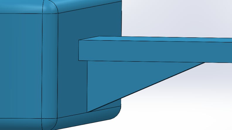
A rib on an FDM CAD file
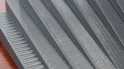
Visible stepping effects as a result of layer by layer growth
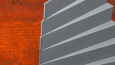
Knife edge features
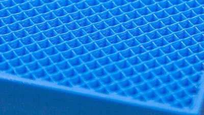
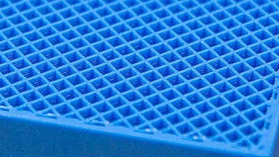
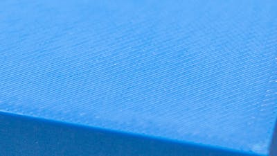
Ultralight: Xometry’s Ultralight infill parts are filled with a single cross-hatch pattern. This is the lightest and least expensive infill option.


