Common Design Mistakes to Avoid in Extruded Parts

In this article, we look at common design pitfalls and provide tips on avoiding them when it comes to metal extruded part design.


Xometry’s metal extrusion services enable you to order custom aluminum extrusions directly from the Xometry Quoting Engine! Things can get tricky when designing a cost-effective and highly manufacturable extrusion die profile. In this article, we will look at common die design mistakes and provide tips to avoid them, so your next extrusion project is setup up for success. Topics we will cover in the sections below include:
- Circumscribing Circle Diameter (CCD)
- Weight-Per-Foot
- Corners & Radii
- Wall Thickness & Balance
- Hollows
- Channel Depth
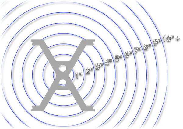
Extrusion profile with a 4"-5" circumscribing circle diameter (CCD)
#1 Not Optimizing for Smallest Circle Size
The size of the smallest circle that the extrusion profile completely fits within is called the circle size or the circumscribing circle diameter (CCD) measurement. This measurement is one of the first things designers should consider when developing a new design. Ideally, you want to aim for the smallest circle size because the container and press size required to make the extrusion is directly tied to the CCD measurement. The larger the circle size, the larger the equipment will need to be. Larger machinery comes with reduced availability and higher operating costs. Optimizing your design for the smallest circle size will be in your best interest to keep costs and lead times as low as possible. Reducing the height of the perimeter fins of a heatsink or redesigning them to spread radially instead of perpendicularly is an example of how you can optimize for a smaller circumscribing circle diameter.
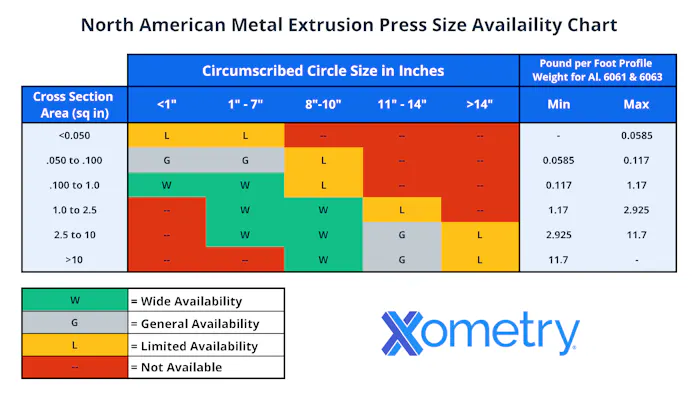
Pro Tip: Try to keep your CCD below 8” for the greatest press availability, as demonstrated by the chart below:
#2 Excessive Weight Per Foot
Another factor that affects press operation and efficiency is the profile weight-per-foot measurement. The larger this measurement is, the more strain it puts on the equipment, which limits the rate of extrusion or necessitates the use of heavier duty machinery. With this in mind, designers should avoid excessive material and thus weight in their designs where possible.
Pro Tip: Keep your profile weight-per-foot between 0.100 lbs/ft and 3lbs/ft.
Calculating Metal Extrusion Profile Weight-Per-Foot
You can use the following basic formula to calculate your profile weight per foot:
(Cross-sectional area (in²) x Density (lb/in³)) * 12 = Theoretical weight per foot
The cross-sectional area is the area of your extrusion’s 2D slice or profile. The simplest way to determine the profile area is by using evaluation or measurement tools in your CAD software. You can find material density by using a lookup chart for the specific alloy you plan to use. In our example below, we calculate a profile wt/ft in aluminum 6061, which has a density of 0.0975 lb/in³.
Example: Calculating profile weight-per-foot in aluminum 6061 of a profile with an area of 2.5in².
(Cross sectional area (in²) x Density (lb/in³)) * 12 = Theoretical weight per foot
2.5in² x 0.0975lb/in³ = 0.24375 pounds per inch
0.24375lbs * 12 inches = 2.925lbs/ft
Extrusion with sharp corners vs. rounded corners
#3 Leaving Corners Sharp
While relatively sharp corners are possible to achieve with the extrusion process, leaving corners sharp can still cause manufacturability issues. When the material extrudes through a die with sharp corners, the material tends to build up in the corners due to differences in material flow rate. Sharp corners can induce stress on the die and lead to uneven heat buildup, which makes it harder to control dimensional stability. Adding corner radii and fillets to your design will ensure better material flow and reduced stress on tooling.
Pro Tip: Do not design radii below 0.015" (0.38mm). The larger you can make your radii, the better; this is especially important as wall thickness increases.
Extrusion with uneven walls vs balanced walls
#4 Uneven Walls
Wall thickness and balance play a vital role in the flow of extruded metal. When wall thicknesses vary greatly, so does the flow of the material. Thin walls will cool more rapidly than thicker walls, which can affect the manufacturer’s ability to precisely control dimensions and tolerances. Making your wall thickness as balanced as possible will ensure uniform cooling and help avoid costly secondary operations.
Pro Tip: Keep wall thickness the same across the profile or as even as possible-- avoid significant variations in wall thickness. As the profile circle size increases, so does the minimum recommended wall thickness.
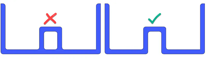
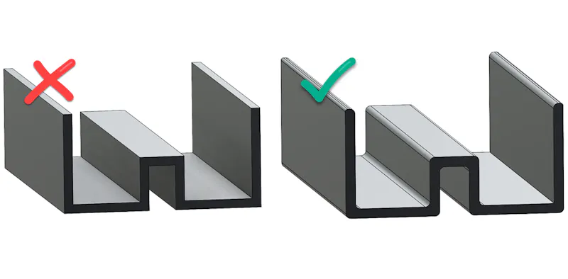
Extrusion profile with excessive hollow vs. optimized design
#5 Excessive Hollows
An extrusion die for parts that contain hollow sections is more complicated and costly to manufacture than ones for parts with solid profiles. When a smaller hollow or cavity is nested inside another hollow, the dimensional stability diminishes in this area, and maintaining tight tolerances becomes exceptionally challenging. Therefore, avoid hollows unless specifically for wall thickness balancing reasons. When designing your part, always ask yourself if there is anything you can do to keep the profile solid while maintaining form, fit, and function.
Pro Tip: You can eliminate nested hollows by adding an opening to make it semi-hollow.
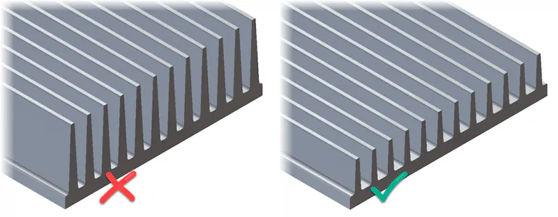
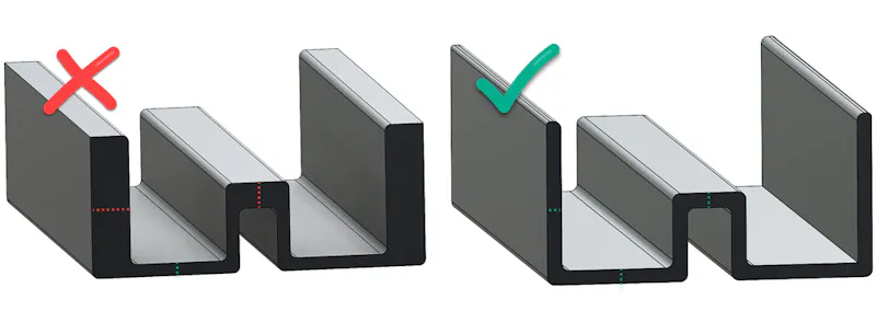
Extrusion profile with a deep channel ratio vs. profile with an ideal ratio
#6 Deep Narrow Channels
Channels that are narrow and deep are challenging to produce. Deep and narrow channels are stressful on the tooling and can lead to die breakage. Designers can mitigate damage by widening channels or reducing their depth.
Pro Tip: Do not go beyond a 3:1 depth to width ratio. In other words, your channel depth should generally not be more than three times the width of the channel.

Disclaimer
The content appearing on this webpage is for informational purposes only. Xometry makes no representation or warranty of any kind, be it expressed or implied, as to the accuracy, completeness, or validity of the information. Any performance parameters, geometric tolerances, specific design features, quality and types of materials, or processes should not be inferred to represent what will be delivered by third-party suppliers or manufacturers through Xometry’s network. Buyers seeking quotes for parts are responsible for defining the specific requirements for those parts. Please refer to our terms and conditions for more information.