Top Die Casting Design Tips

Quick tips to help you improve the design and cost of your die cast parts.


We proudly offer die casting services to our customers through the Xometry Instant Quoting Engine! Whenever we receive a request for a new die casting project, one of the first things our engineers do is review the design for manufacturability. A design unsuitable for the intended manufacturing process can result in production delays and increased project costs. With that in mind, we have compiled some top tips to assist you in coming up with die casting part designs that are both manufacturable and cost-effective so you can hit the ground running and have the highest chance of success with your project. Below is a list of the topics we will cover in this article:
- Fillets and Radii
- Wall Thicknesses
- Ribs and Metal Savers
- Holes and Windows
- Parting Lines
- Die Cast Surface Finish Classes
Die Casting Design Principles
Before we get into the specific design tips, let’s take a look at the primary principles that make for successful die casting:
- The molten metal can easily flow through the mold, filling it to produce a solid part.
- The metal solidifies evenly and quickly.
- The part ejects without damaging itself or the tooling.
- The part design minimizes the complexity of the tooling required.
- The part function is prioritized over its shape.
- Tolerances should be kept as open as possible without affecting the fit, form, or function.
By keeping these principles in mind and utilizing the tips below, you will be well on your way to producing a design that can be reliably and economically made. If you have an upcoming die casting project, feel free to start a quote with us today! Our representatives and subject matter experts are here to help guide you through the process and help answer any questions you may have.
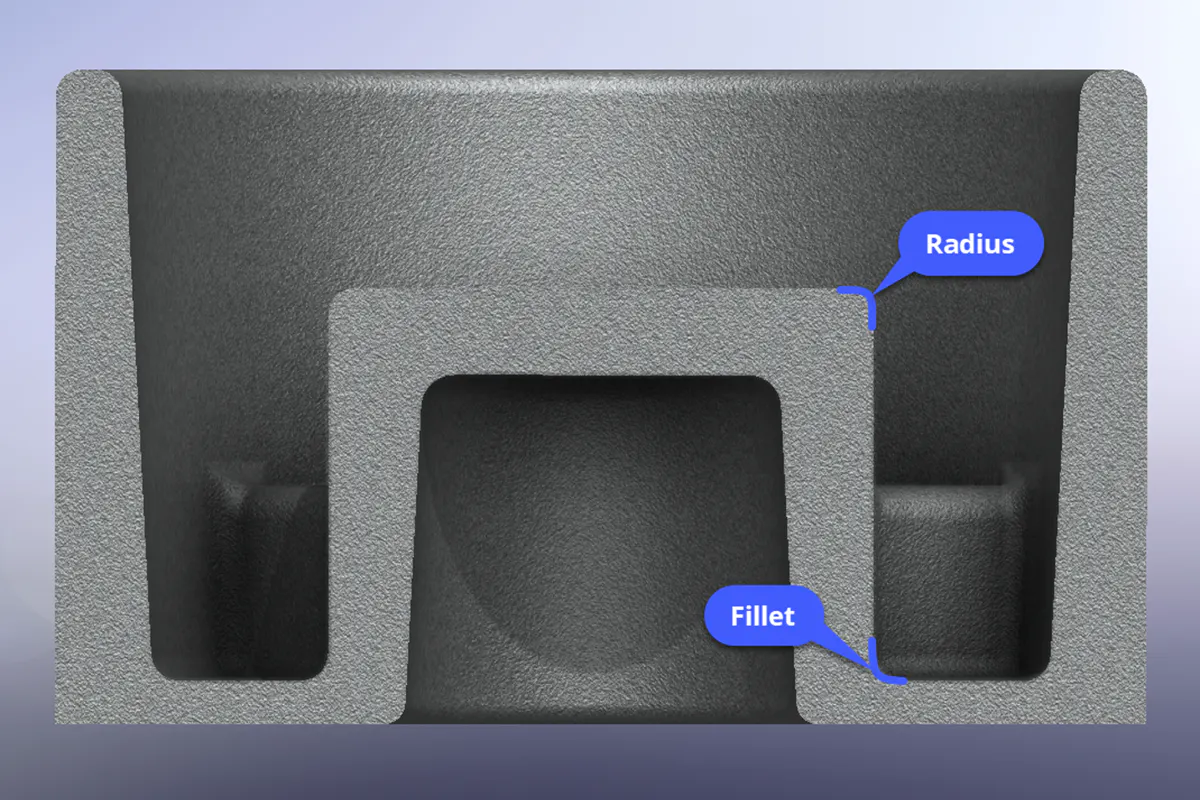
Examples of fillets and radii
Fillets and Radii
Implementing both fillets and radii in your design can be beneficial in several ways. Firstly, they help the metal evenly flow through all areas of the part and reduce concentrated areas of heat around corners and transitions. These are also important features to prevent cold shuts, caused when the metal begins solidifying before it has completely filled the mold cavity. Components that cool evenly lessen the stress on the tooling, thus increasing its lifetime and reducing maintenance. Fillets can also reduce stress concentrations, especially where intersecting features would otherwise create sharp corners. Here are some further guidelines when it comes to adding fillets and radii:
- Add fillets or radii to sharp edges and corners.
- The deeper the corner or pocket, the larger the fillet should be.
- Fillets create smooth transitions between features that promote metal flow and structural integrity. Radii should be generous on intersecting features.
- Constant-radius fillets help maintain edge continuity and smoothness of the part.
- Draft angles are required when the fillet is perpendicular to the parting line. The draft of the intersecting surface will determine the amount of draft needed.
Wall Thicknesses
When it comes to wall thicknesses, the most crucial aspect is uniformity. Keeping the walls of the part uniform will help promote metal flow and uniform cooling. Areas with uneven wall thicknesses can cause different shrinkage rates, leading to defects in the part, such as sink marks or cracks. Here are some other considerations to make when it comes to wall thicknesses:
- Molten metal flows more freely with thicker walls.
- Certain alloys such as zinc can produce parts with thinner walls.
- Avoid prominent protruding features that significantly increase wall thickness, which can cause uneven and slower cooling rates.
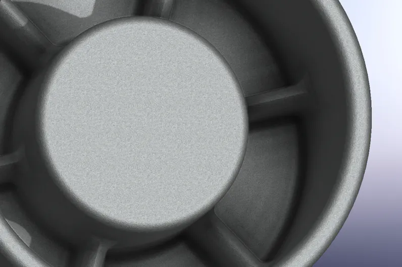
Part with ribs and metal saving features
Ribs and Coring
Ribs are structural features that provide several benefits in die cast parts. Their primary purpose is to provide additional rigidity and strength, especially to areas with thin walls. Ribs also assist the molten metal flow, allowing it to reach and fill connected areas more quickly.
Adding corings, such as the space between ribs or walls, helps reduce material as a metal-saver and provides better cast parts. The purpose of coring is to displace the casting alloy, reducing material usage and resulting in a lighter-weight part. With the proper use of ribs and coring, you can avoid areas of concentrated heat caused by excessive material buildup while also reducing the weight of the part and maintaining its strength. When incorporating ribs and cored features into your design, it’s essential to keep the following in mind:
- Designers should add ribs onto thin-walled sections.
- Design for an odd number of ribs to better distribute internal stresses and avoid forming thick intersections.
- Add fillets to ribs and edges of metal savers to reduce sharp corners and assist with metal flow.
- Avoid having too many ribs too close together, as this can affect the effectiveness of metal savers.
- Include generous draft on the sides of metal saver pockets to assist with mold release and prevent tool wear.
Design Guide: Die Casting
Holes and Windows
Special consideration should be given to hole and window features, as they present their own unique challenges with the die casting process. The inside surfaces of holes and windows tend to adhere to surfaces of the steel die during the cooling process. This can impact the ejection mechanism and make it harder to release the part from the die, contributing to tool wear and part defects. Additionally, holes and windows can impede metal flow through the casting. Additional techniques such as bridge features or runners can be used for larger windows to ensure proper metal flow; however, this can add extra steps and cost to trim out these features after casting. If your design requires holes and windows, the design guidelines below will help keep your part manufacturable:
- Holes and windows require the highest draft compared with other features.
- Perimeters of holes and windows should be filleted.
- In some cases, it may be better to post-machine holes; however, this will add manufacturing time.
Post-Machined Features
Post-machining is common with many die cast components. Because die cast parts typically hold tight tolerances and can involve complex shapes, most post-machined features are minor. Machining does add costs per part but also can mitigate tool complexity and guarantee critical tolerances or surface features where required. When considering post-machined features, keep the following in mind:
- Post-machined features follow the same design considerations of CNC machining services.
- The more machining operations, the higher the cost per part.
- Call out machining features wherever tolerances are beyond die casting conditions. For example, a bearing fit.
- Provide two designs and technical drawings: the first being the as-cast part and the second for the final finished workpiece.
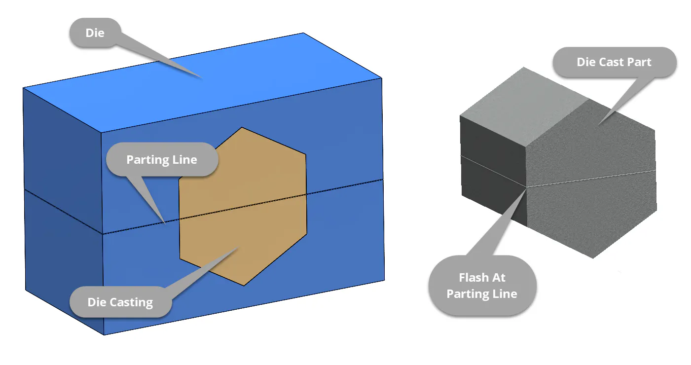
Example of parting line and flash in die casting
Parting Lines
Parting lines are where the die halves meet and interface with each other. When designing your parts, the parting line locations are one of the first aspects to consider. Parting lines can be straight or broken depending on the geometry and die components required to create them. When it comes to the parting line locations, here are the key aspects to consider:
- Parts with straight parting lines will usually be less expensive than one that requires broken parting lines since less complex tooling is needed.
- Quality along parting lines is more difficult to control; therefore, you should avoid having it cross critical or tight tolerance features.
- Parting lines often exhibit flash, a thin web or fin of material that occurs due to the clearances needed for die operation. Flash is removed during trimming, and it should be easily accessible.
Die Casting Surface Finish Classses
The as-cast external surface finish classification should be specified in your design. The class you choose can significantly influence the end cost as higher-grade finishes require additional steps and a more sophisticated die design. That said, you should aim to select the lowest classification that meets your intended application to yield lower costs.
The North American Die Casting Association (NADCA) has guidelines to help you classify your surface finishing requirements in a general sense. Please reference the chart below for these classification guidelines. Note that this is useful for general type classification, and final finish quality requirements are agreed upon between the customer and manufacturer.
As-Cast Surface Finish Classification Chart
| Class | As-Cast Finish | Final Finish or End Use |
|---|---|---|
Class Class 1 - Utility Grade | As-Cast Finish No cosmetic requirements. Surface imperfections (cold shut, rubs, surface porosity, lubricant build-up, etc.) are acceptable | Final Finish or End Use Used as-cast or with protective coatings; anodize (non-decorative), chromate |
Class Class 2 - Functional Grade | As-Cast Finish Surface imperfections (cold shut, rubs, surface porosity, etc.), that can be removed by spot polishing or can be covered by heavy paint, are acceptable. | Final Finish or End Use Decorative coatings: lacquers, enamels, plating (Al), chemical finish, polished finish |
Class Class 3 - Commercial Grade | As-Cast Finish Slight surface imperfections that can be removed by agreed upon means are acceptable | Final Finish or End Use Structural parts (high-stress areas), plating (Zn), electrostatic painting, transparent paints |
Class Class 4 - Consumer Grade | As-Cast Finish No objectionable surface imperfections. Where surface waviness (flatness), noted by light reflection, is a reason for rejection special agreement should be reached with the die caster. | Final Finish or End Use Special decorative parts |
Class Class 5 - Superior Grade | As-Cast Finish Surface finish, applicable to limited areas of the casting and dependent on alloy selected, to have an average value in micro inches as specified on print. | Final Finish or End Use O-ring seats or gasket areas |
Classes 1-4 relate to cosmetic surfaces. Class 5 relates to select areas where specific surface finish limitations are required.