CNC programming is a translation of sorts between humans and computers. In the process, you’ll be taking a computer-aided design (CAD) model that’s oftentimes drawn up by a human and turning it into a set of instructions that a machine will be able to read before making it into a reality. There are loads of reasons why an employee or a business as a whole would be interested in CNC programming, especially if CNC machining and its myriad of processes are part of your day-to-day activities. There’s a lot to cover on this topic, so let’s get cracking.
What is CNC Programming?
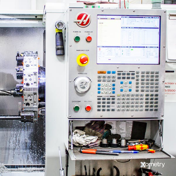
CNC programming involves you or a fellow colleague using computer-aided manufacturing (CAM) software to convert a CAD file into a language that a CNC machine can read, whether it’s a cutting, milling, or turning tool (although they can also be programmed manually). Here’s an example of a CNC programming console:

It’s an interesting process of getting CAD models into strings of information that your machine will then begin following. It starts with someone breaking down a 3D CAD model by creating tool paths that analytically describe all the part-to-be’s features, including geometry, holes, contours, and slots. The CAM software will then make step-by-step instructions in the CNC machine’s language (this is called G-code) so that it’s understandable and nothing gets lost in translation. Once the machine is fed this G-code, it can then get a move on and make the part to the manufacturing standards mentioned within the code.
Important Codes for CNC Programming
While “G-code” is the most commonly used term to describe CNC programming’s language, this can be broken down into several other types. G-code may be referring to all of the programming, but it also refers solely to the geometry part of the code. That’s why it’ll be handy to know the following terms, too:
- D-codes: This type of code can point to two different distances, either the machine’s tool offset from the center line or the amount that it sticks out from the tool holder.
- F-codes: The “F” makes it easy to remember that this type of code refers to the feed rate and the different speeds the tool will need to run at while machining.
- G-codes: These share the geometry of the model with the machine to let it know exactly where and when to start, stop, and how it should move between points.
- M-codes: This is a term for code that doesn’t fit into any of the other code categories. M is for “miscellaneous,” covering aspects like coolant and spindle control.
- N-codes: These keep track of machine code for manually written conversions. They’re not needed if you’re using CAM software to write and convert instructions.
- S-codes: These are for the different spindle speeds that the CNC machine will need to reach, maintain, and switch between. (It’s easy to remember, too: S = spindle speed!)
- T-codes: These codes help machines understand what type of tool is needed for specific areas of a part.
Writing Your Own CNC Code
If you’re not formally trained in the art of CNC code, you’ll have quite a learning curve in front of you when it comes to writing your own code. It’s doable (with a lot of effort and head-scratching), but we recommend getting some professional lessons in. These will give you a good understanding of CNC machining and the programming necessary for different processes. You’ll also learn all the ins and outs of CAD/CAM software and the languages that are used between computers and machines. Once you have this background knowledge and experience, you’ll most likely take the following steps for coding CNC language:
- Export: The first step is exporting the model you created in the CAD program to your CAM software. There are newer applications nowadays that have integrated these two types of programs, so check and see if yours has this capability.
- Tool paths: Next, you can either allow the CAM software to draft up tool paths for the intended features or do so manually, which is usually better for basic parts.
- Verification: Double-check that the tool paths are correct by testing them through a simulation within the application you’re using (don’t worry if the program doesn’t have that feature; there are many third-party verification software options available).
- Download to the CNC Machine: Once the code is created and verified, it’s ready to be downloaded to the CNC machine with a flash drive or a local connection. The machine will then be able to read through the code and get to work.
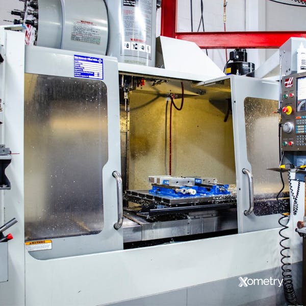
Below is an image of a 3-axis CNC machine, which is one example of a tool that uses CNC programming and codes. CNC machines can process all sorts of materials, including plastics, composites, and metals.

Types of CNC Programming
We’ve listed out the three main CNC programming methods that are beneficial to most types of CNC machining — although there are nicher types that exist, too.
1. Manual
Manual programming is exactly how it sounds and is done by a programmer manually inputting information into the CNC machine’s control console. It’s the most basic form and isn’t an ideal method when you’re trying to program complex geometries, features, and actions. This method has a higher chance of error, quite simply because the programmer is human (we assume). It also can’t alert you if mistakes have been made or if something is about to go belly up. Despite this, the method is still being used because it’s quite handy for making simple parts.
2. Computer-Aided Manufacturing
This is the most common type of CNC programming and can make both simple and complex parts, thanks to its accuracy and quick software. It can give programmers a visualization of a project to better understand it and catch any potential errors. Using this software, you’ll be able to see the tool paths and the software will also alert you to mistakes. CAM programs are notoriously pricey, but they can save a lot of time, energy, and money as they can do all the translating needed between CNC machines.
3. Conversational
This is one of the more interesting and user-friendly programming options available. This type of software comes built into specific CNC machines and doesn’t require the programmer to input G-code. Instead, a programmer can answer questions prompted by the system or write things down in their standard language which the machine’s software will convert automatically. Currently, it’s used for simpler parts, but there’s certainly room in the industry for more advanced conversational software to come in.
Examples of Software
The applications out there are always changing and evolving, but below is a list of some of the most common software programs you’ll likely use these days:
- Mastercam
- Vectric
- Meshcam
- Fusion 360
- Solidworks
- Carbide 3D
- HyperMILL
How Xometry Can Help
At Xometry, we offer several types of CNC-specific options for businesses, which make the most of CNC programming. Aside from CNC machining, we have CNC milling, CNC turning, CNC routing, and medical CNC in our repertoire. Get a free quote on our website today for the service that makes the most sense for you.
Disclaimer
The content appearing on this webpage is for informational purposes only. Xometry makes no representation or warranty of any kind, be it expressed or implied, as to the accuracy, completeness, or validity of the information. Any performance parameters, geometric tolerances, specific design features, quality and types of materials, or processes should not be inferred to represent what will be delivered by third-party suppliers or manufacturers through Xometry’s network. Buyers seeking quotes for parts are responsible for defining the specific requirements for those parts. Please refer to our terms and conditions for more information.


