Everything You Need to Know About Gear Cutting


A guide to this important gear-making process


The term “gear cutting” refers to the various methods that are used to make gears out of gear blanks (a block that looks like the final gear shape). In this article, we’ll explain exactly how it’s done, the various processes, and also the different types of gears you can make.
What is Gear Cutting?
Gear cutting is a process used to make gears. It works with a cutting tool that’s mounted onto a milling machine and cuts one tooth at a time. There are many different types of gear-cutting processes used in manufacturing to make various gear types, and they all work on the same basic principle: giving a gear blank some teeth so that the gears can lock with one another to transmit a rotational force that makes them go round and round. Despite being limited when it comes to certain features and sizes, gear cutting is a fast, precise, and cost-effective way to make a gear, and allows you to make many gear types. Sometimes, though, you’ll need special tools or machines. It also produces quite a bit of waste.
Gear Cutting Processes
The type of gear cutting process you choose will ultimately depend on which type of gear you need to make, along with your production volume, budget, and design tolerance. Other methods, like casting or stamping, use forming instead of cutting. Gear cutting allows you to make worm, bevel, spur, helical, or herringbone gears, but there isn’t just one way of doing it. Read on to learn more about the different cutting methods.
Gear Grinding
This method uses a rotating abrasive wheel to remove material from a gear blank; when the wheel makes contact with the blank, it transfers its profile into the gear. It’s a generally slower method and can be quite expensive, but it’s extremely precise. The image below shows you what gear grinding looks like. The pink wheel is the grinding disc, and the gear blank is on the right:
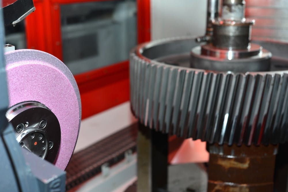
Gear grinding.
Image Credit: Shutterstock.com/Dovzhykov Andriy
Gear Shaping
This is one of the oldest methods of making gears. The profile of the cutter needs to be the same shape and geometry as the teeth you want to cut. By using a linear motion (cutting and returning), the tool cuts away material from the blank. The gear shaping tool has the same pitch as what’s needed for the gear tooth, and it can also be used on gears that need a varying number of teeth. Gear shaping usually has a shorter production time, can produce consistent results, and can create most types of gear, except worm gear. It’s not the most accurate, but many choose this for medium-sized production runs.
Gear Finishing
If you need a good surface finish and accurate teeth, gear finishing is recommended. It uses an abrasive wheel to smooth the meshing surfaces of the gear. It’s similar to gear grinding, but the wheel used is much finer so doesn’t remove as much material.
Gear Broaching
This is a quick method that uses a broach (a cutting tool with lots of teeth) that’s specifically designed for gear teeth. Gear broaching can be done on any lathe, milling machine, machining center, or turning machine, but it’s quite expensive because each broach is designed to cut a specific style or size of tooth. Its price, coupled with the fact it’s one of the fastest gear-cutting processes, is the reason it’s mainly used for high-production parts. Here’s what it looks like:

Gear broaching.
Image Credit: Shutterstock.com/Dmitry Kalinovsky
Gear Hobbing
This process uses a helical cutting tool and is also fast, accurate, and probably best suited for medium to high production volumes. It’s done using a CNC hobbing machine, in which both the tool and gear blank are rotated and brought together until all the teeth are cut. This is actually the most accurate way to make gears, but it can’t be used to make internal or spline gears.
Gear Milling
Gear milling is done using a milling machine and a form-cutting tool, which spins to cut each tooth individually. After cutting each tooth, the cutter will move away, allow the gear blank to rotate, and then move back in for the next cut. You can probably tell that this type of gear cutting isn’t very fast, and so it’s best for smaller production runs. It’s also not very precise. It’s very appealing, though, when you need to make one-off, low-production custom parts without having to get special tools. The following image is what gear milling looks like, and the form tool is in the upper middle:
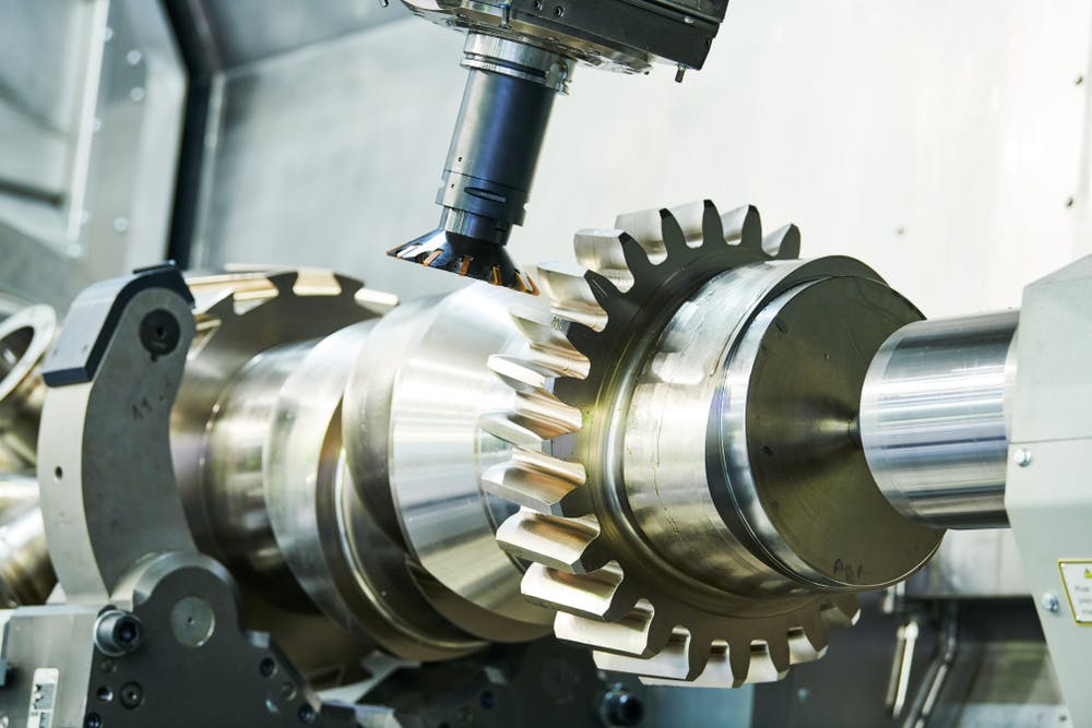
Industrial gear milling.
Image Credit: Shutterstock.com/Dmitry Kalinovsky
How to Gear Cut
Gear cutting isn’t too difficult, but some cuts are harder to make than others. The right tools and some experience can make the process a whole lot easier. Rest assured, though, that gear cutting is not considered one of the harder machining processes. Naturally, every method will vary slightly, but let’s take gear hobbing as an example.
The first thing you’ll want to do is choose the right hob for the gear. Each spindle cuts a different tooth size and pitch. You’ll then have to fit the hob to the machine’s tool spindle, and the gear blank to the work spindle. Set the angle and speed ratio you want, then engage the machine drive and bring the spindle in contact with the blank. You’ll also have to make sure there’s enough coolant while you’re cutting. That’s pretty much it. Once you’ve finished cutting, take out the gear for any post-processing.
To make sure your gear-cutting journey is a success, try some of our tips and tricks below:
- Consider what you need and choose the right type of gear-cutting method
- Take your time calculating the correct cutting and feed speeds
- Make sure the work gets plenty of lubrication during cutting (this varies with each method)
- Cut the smaller gears first to save yourself some material and time in case of a mistake
Different Types of Gears
The various gear-cutting techniques available can help you make different types of gears. Not all gears are the same; some types are better suited for certain applications than others. The type of gear and the gear cutting method you choose will depend on your budget, and specific gear needs (i.e., power transmission, friction, noise levels, etc.). The different types of gears you can cut are described below.
Worm Gear
A worm gear has a single tooth that wraps around a cylindrical body. This type of gear (usually made from hard material) interlinks with a worm wheel (made from soft material), which looks quite similar to a spur gear. Because the worm gear rotates a lot against the worm wheel, this type of gear usually undergoes a lot of friction. It’s also quite compact and provides decent speed reduction. For these reasons, worm gears are often found in small engines, conveyors, and ship rudders. Here’s an example of what a worm gear and worm wheel look like (the gear is on top):


Bevel Gear
Bevel gears are designed to transmit power between two shafts with intersecting axes. Although bevel gears count as a single category, there are some subtypes including straight, spiral, zerol, hypoid, and mitre. They have a large surface and aren’t cheap to make. That’s why they’re often used in applications like power plants, transmissions, helicopter power transmissions, and vehicle differential gears. Here’s what they look like:

Spur Gear
Spur gears have pitched surfaces around their circumference. As you’ll notice in the image below, they also have shafts and teeth lines that are parallel to the axis of rotation. They’re the most common type of gear and relatively easy to make. They don’t have an axial load and are therefore commonly used in things like motors, transmissions, and machine tools. Here’s how they look:

Helical Gear
Helical gears are somewhat similar to spur gears in terms of having pitched teeth around their circumference. The main difference is that helical gear teeth are not parallel to the axis of rotation, but wrap around the circumference. This helps helical gears transmit higher loads with less noise, which is why a lot of Xometry customers choose it for their high-speed applications. You’ll need to use thrust bearings with this method because the teeth are slanted and push sideways when they spin, creating an extra force (axial load). This type of gear is often used in elevators, conveyor belts, and earth-moving equipment. This is what it looks like:

Herringbone Gear
Herringbone gears have many of the advantages of helical gears, but they reduce the thrust load. You’ll notice in the image below that they basically look like two helical gears that have opposite tooth-winding directions. Generally, herringbone gears are made as one piece, but because this can be expensive, it’s not uncommon for two helical gears to be joined using a machined center. This type of gear is commonly used in lathes and milling machines, as well as gas turbines, and marine propulsion systems. Here’s an example of a herringbone gear:
Gear Cutting vs. Grinding
This is a common question we get here at Xometry. Gear cutting is better than grinding when it comes to making gears because it’s generally faster and cheaper. Grinding is the clear winner when it comes to precision and creating smooth surface finishes, but, as that’s not the most important factor when making gears, gear cutting is the way to go.
Gear Cutting vs. Milling
Some gear-cutting methods are forms of milling, so naturally, they have some things in common. But they’re also different in many ways. Here are some of their biggest differences:
- Milling generally makes one cut at a time, but gear cutting can make several at once.
- Milling tools tend to be more expensive.
- Milling is more versatile in that it can be used to cut holes, slots, undercuts, fillets, and many other things. Gear-cutting, though; just gear teeth.
- Quite often, milling will require deburring, but gear cutting won’t.
How Xometry Can Help
We provide a wide range of manufacturing capabilities here at Xometry, including CNC machining, 3D printing, laser cutting, and other value-added services for anything you need. If you’d like to find out more about gear cutting or get a free no-obligation quote, a Xometry representative would be happy to hear from you.
Disclaimer
The content appearing on this webpage is for informational purposes only. Xometry makes no representation or warranty of any kind, be it expressed or implied, as to the accuracy, completeness, or validity of the information. Any performance parameters, geometric tolerances, specific design features, quality and types of materials, or processes should not be inferred to represent what will be delivered by third-party suppliers or manufacturers through Xometry’s network. Buyers seeking quotes for parts are responsible for defining the specific requirements for those parts. Please refer to our terms and conditions for more information.