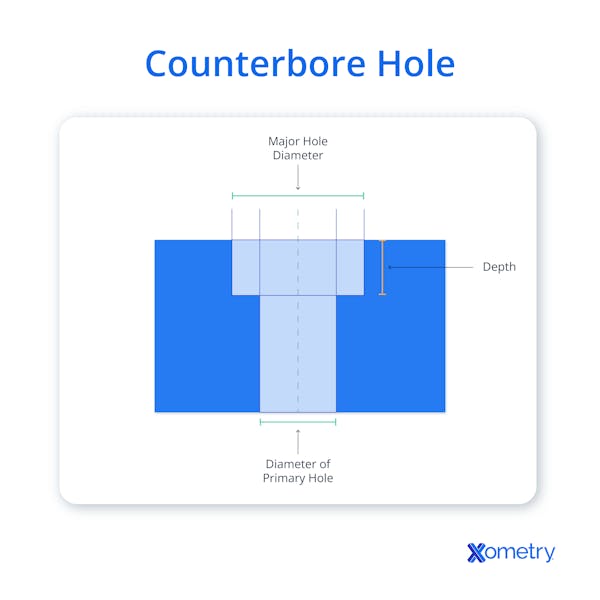
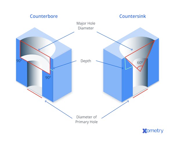
Many products seek to improve their appearance by “burying” fasteners. One way to achieve this is with a counterbore. A counterbore involves adding a stepped hole, that recesses the head of the fastener (and washers where fitted). This cavity is cylindrical and generally flat/perpendicular at its lower face, although counterbores can be used for countersunk fasteners, for specialist reasons.
The use of counterboring conceals the head of a fastener completely, improving the appearance and allowing sliding parts to be unobstructed. Fastener heads can be made to lie flush with or under the face of the part. Where fasteners are to be entirely concealed, an additional, deep counterbore allows room for a dowel to be inserted after fixing. Where the selected fastener requires a peripherally located tool (such as a hex socket), the counterbore must be large enough for the socket to fit on the fastener until it is fully tight.
This article will further discuss what counterbore holes are, how to choose the right tap, as well as the applications and uses.
How To Drill a Counterbore Hole
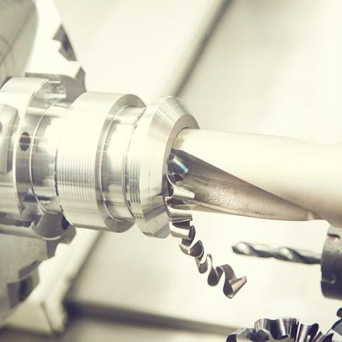
In CNC machining of metals and plastics, the counterbore operation is generally performed by a non-specialist cutter of a larger diameter in a secondary operation. The CNC machine obviates the need for a mechanical depth limit, as this is machine-controlled. Automation also makes centering of the counterbore a function of machine programming rather than it being a hit-or-miss process, so there is no requirement for the counterbore operation to physically locate the initial hole for a fully centered start. Counterbores can precede hole drilling in these circumstances, which may reduce the need for tool changes or traverses, speeding up operations.

Choosing the Right Tap for a Counterbore Hole
Where the counterbored hole is formed/drilled through to the other side of the part, the tap required for threading such a hole is a taper or middle type. These two forms of tap have the initial threads ground away, allowing the tap to enter the hole and correctly center from the start of tapping/thread cutting.
For a through hole, the selection of taper or middle taps depends on the depth of the hole to be tapped. There must be enough total length of unaltered tap and shank combined to allow the tap to penetrate deeply enough to complete the thread all the way through the part.
Where the hole is blind, tapping requires a two-stage operation. The thread is initiated with a taper or middle tap and then completed with a bottoming tap to the required depth. The choice between taper and middle taps is driven by the blind hole depth. Where its use is possible, the taper tap gives a softer and more certain start to the thread cutting. But, if the taper prevents effective (full depth) cutting as it is longer than the blind hole is deep, it is necessary to use a middle tap.
Applications and Uses of Counterbore Holes
Counterbores are most commonly used for the aesthetic concealment of fasteners, to render a product surface more smooth. Where the counterbore is then plugged or capped, this essentially makes the fasteners invisible, taking the improved appearance to its logical conclusion. This generally applies to fasteners that are not at risk of requiring later removal.
Additional practical reasons for counterbore holes to bury the heads of fasteners are: in moving equipment, to remove obstacles and reduce the need for clearances; in walkways, and on stairs and gantries, to remove obstructions and trip hazards; and to bury fastener heads, where an additional component must overlay the fastener, removing the need for precise relief holes/recesses in the overlying part.
Counterbore Hole Size Charts
Table 1 below summarizes the counterbore hole size for socket head fasteners:
| Fastener Size | Pilot hole diameters (inches) | Pilot hole diameters (inches) | Pilot hole diameters (inches) | Counterbore details (inches) | Counterbore details (inches) |
|---|---|---|---|---|---|
Fastener Size
| Pilot hole diameters (inches) Close Fit | Pilot hole diameters (inches) Normal Fit | Pilot hole diameters (inches) Loose Fit | Counterbore details (inches) Diameter | Counterbore details (inches) Depth |
Fastener Size #0 | Pilot hole diameters (inches) 1/15 | Pilot hole diameters (inches) 6/79 | Pilot hole diameters (inches) 3/32 | Counterbore details (inches) 1/8 | Counterbore details (inches) 6/79 |
Fastener Size #1 | Pilot hole diameters (inches) 3/37 | Pilot hole diameters (inches) 4/45 | Pilot hole diameters (inches) 8/77 | Counterbore details (inches) 5/32 | Counterbore details (inches) 2/23 |
Fastener Size #2 | Pilot hole diameters (inches) 3/32 | Pilot hole diameters (inches) 7/69 | Pilot hole diameters (inches) 7/62 | Counterbore details (inches) 3/16 | Counterbore details (inches) 5/49 |
Fastener Size #3 | Pilot hole diameters (inches) 5/47 | Pilot hole diameters (inches) 8/69 | Pilot hole diameters (inches) 9/70 | Counterbore details (inches) 7/32 | Counterbore details (inches) 10/87 |
Fastener Size #4 | Pilot hole diameters (inches) 3/25 | Pilot hole diameters (inches) 9/70 | Pilot hole diameters (inches) 14/97 | Counterbore details (inches) 7/32 | Counterbore details (inches) 11/86 |
Fastener Size #5 | Pilot hole diameters (inches) 9/64 | Pilot hole diameters (inches) 5/32 | Pilot hole diameters (inches) 11/64 | Counterbore details (inches) 1/4 | Counterbore details (inches) 11/78 |
Fastener Size #6 | Pilot hole diameters (inches) 2/13 | Pilot hole diameters (inches) 10/59 | Pilot hole diameters (inches) 5/27 | Counterbore details (inches) 9/32 | Counterbore details (inches) 2/13 |
Fastener Size #8 | Pilot hole diameters (inches) 9/50 | Pilot hole diameters (inches) 10/51 | Pilot hole diameters (inches) 13/61 | Counterbore details (inches) 5/16 | Counterbore details (inches) 9/50 |
Fastener Size #10 | Pilot hole diameters (inches) 15/73 | Pilot hole diameters (inches) 21/95 | Pilot hole diameters (inches) 5/21 | Counterbore details (inches) 3/8 | Counterbore details (inches) 8/39 |
Fastener Size 1/4 | Pilot hole diameters (inches) 17/64 | Pilot hole diameters (inches) 9/32 | Pilot hole diameters (inches) 19/64 | Counterbore details (inches) 7/16 | Counterbore details (inches) 25/89 |
Fastener Size 5/16 | Pilot hole diameters (inches) 21/64 | Pilot hole diameters (inches) 11/32 | Pilot hole diameters (inches) 23/64 | Counterbore details (inches) 17/32 | Counterbore details (inches) 12/35 |
Fastener Size 3/8 | Pilot hole diameters (inches) 25/64 | Pilot hole diameters (inches) 13/32 | Pilot hole diameters (inches) 27/64 | Counterbore details (inches) 5/8 | Counterbore details (inches) 28/69 |
Fastener Size 7/16 | Pilot hole diameters (inches) 29/64 | Pilot hole diameters (inches) 15/32 | Pilot hole diameters (inches) 31/64 | Counterbore details (inches) 23/32 | Counterbore details (inches) 38/81 |
Fastener Size 1/2 | Pilot hole diameters (inches) 17/32 | Pilot hole diameters (inches) 9/16 | Pilot hole diameters (inches) 39/64 | Counterbore details (inches) 13/16 | Counterbore details (inches) 43/81 |
Fastener Size 5/8 | Pilot hole diameters (inches) 21/32 | Pilot hole diameters (inches) 11/16 | Pilot hole diameters (inches) 47/64 | Counterbore details (inches) 1 | Counterbore details (inches) 61/93 |
Fastener Size 7/8 | Pilot hole diameters (inches) 29/32 | Pilot hole diameters (inches) 15/16 | Pilot hole diameters (inches) 1 1/32 | Counterbore details (inches) 1 3/8 | Counterbore details (inches) 77/85 |
Fastener Size 1 | Pilot hole diameters (inches) 1 1/32 | Pilot hole diameters (inches) 1 3/32 | Pilot hole diameters (inches) 1 5/32 | Counterbore details (inches) 1 5/8 | Counterbore details (inches) 1 1/16 |
Fastener Size 1 1/4 | Pilot hole diameters (inches) 1 9/32 | Pilot hole diameters (inches) 1 31/90 | Pilot hole diameters (inches) 1 7/16 | Counterbore details (inches) 2 | Counterbore details (inches) 1 5/16 |
Fastener Size 1 1/2 | Pilot hole diameters (inches) 1 9/16 | Pilot hole diameters (inches) 1 5/8 | Pilot hole diameters (inches) 1 47/64 | Counterbore details (inches) 2 3/8 | Counterbore details (inches) 1 9/16 |
Fastener Size 1 3/4 | Pilot hole diameters (inches) 1 13/16 | Pilot hole diameters (inches) 1 7/8 | Pilot hole diameters (inches) 2 | Counterbore details (inches) 2 3/4 | Counterbore details (inches) 1 13/16 |
Fastener Size 2 | Pilot hole diameters (inches) 2 1/16 | Pilot hole diameters (inches) 2 1/8 | Pilot hole diameters (inches) 2 1/4 | Counterbore details (inches) 3 1/8 | Counterbore details (inches) 2 1/16 |
Table Credit: https://engineersbible.com/
Table 2 below shows the counterbore hole size chart for socket cap head fasteners:
| Fastener Size | Pilot hole diameters (mm) | Pilot hole diameters (mm) | Pilot hole diameters (mm) | Counterbore details (mm) | Counterbore details (mm) |
|---|---|---|---|---|---|
Fastener Size
| Pilot hole diameters (mm) Close Fit (H12) | Pilot hole diameters (mm) Normal Fit (H13) | Pilot hole diameters (mm) Loose Fit (14) | Counterbore details (mm) Diameter | Counterbore details (mm) Depth |
Fastener Size M1.6 | Pilot hole diameters (mm) 1.7 | Pilot hole diameters (mm) 1.8 | Pilot hole diameters (mm) 2 | Counterbore details (mm) 3.5 | Counterbore details (mm) 1.8 |
Fastener Size M2 | Pilot hole diameters (mm) 2.2 | Pilot hole diameters (mm) 2.4 | Pilot hole diameters (mm) 2.6 | Counterbore details (mm) 4.4 | Counterbore details (mm) 2.2 |
Fastener Size M2.5 | Pilot hole diameters (mm) 2.7 | Pilot hole diameters (mm) 2.9 | Pilot hole diameters (mm) 3.1 | Counterbore details (mm) 5.5 | Counterbore details (mm) 3 |
Fastener Size M3 | Pilot hole diameters (mm) 3.2 | Pilot hole diameters (mm) 3.4 | Pilot hole diameters (mm) 3.6 | Counterbore details (mm) 6.5 | Counterbore details (mm) 3.5 |
Fastener Size M4 | Pilot hole diameters (mm) 4.3 | Pilot hole diameters (mm) 4.5 | Pilot hole diameters (mm) 4.8 | Counterbore details (mm) 8 | Counterbore details (mm) 4.8 |
Fastener Size M5 | Pilot hole diameters (mm) 5.3 | Pilot hole diameters (mm) 5.5 | Pilot hole diameters (mm) 5.8 | Counterbore details (mm) 10 | Counterbore details (mm) 5.8 |
Fastener Size M6 | Pilot hole diameters (mm) 6.4 | Pilot hole diameters (mm) 6.6 | Pilot hole diameters (mm) 7 | Counterbore details (mm) 11 | Counterbore details (mm) 6.8 |
Fastener Size M8 | Pilot hole diameters (mm) 8.4 | Pilot hole diameters (mm) 9 | Pilot hole diameters (mm) 10 | Counterbore details (mm) 15 | Counterbore details (mm) 8.8 |
Fastener Size M10 | Pilot hole diameters (mm) 10.5 | Pilot hole diameters (mm) 11 | Pilot hole diameters (mm) 12 | Counterbore details (mm) 18 | Counterbore details (mm) 10.8 |
Fastener Size M12 | Pilot hole diameters (mm) 13 | Pilot hole diameters (mm) 13.5 | Pilot hole diameters (mm) 14.5 | Counterbore details (mm) 20 | Counterbore details (mm) 12.8 |
Fastener Size M16 | Pilot hole diameters (mm) 17 | Pilot hole diameters (mm) 17.5 | Pilot hole diameters (mm) 18.5 | Counterbore details (mm) 26 | Counterbore details (mm) 16.8 |
Fastener Size M20 | Pilot hole diameters (mm) 21 | Pilot hole diameters (mm) 22 | Pilot hole diameters (mm) 24 | Counterbore details (mm) 33 | Counterbore details (mm) 21 |
Fastener Size M24 | Pilot hole diameters (mm) 25 | Pilot hole diameters (mm) 26 | Pilot hole diameters (mm) 28 | Counterbore details (mm) 40 | Counterbore details (mm) 25 |
Fastener Size M30 | Pilot hole diameters (mm) 31 | Pilot hole diameters (mm) 33 | Pilot hole diameters (mm) 35 | Counterbore details (mm) 50 | Counterbore details (mm) 31 |
Fastener Size M36 | Pilot hole diameters (mm) 37 | Pilot hole diameters (mm) 39 | Pilot hole diameters (mm) 42 | Counterbore details (mm) 58 | Counterbore details (mm) 37 |
Fastener Size M42 | Pilot hole diameters (mm) 43 | Pilot hole diameters (mm) 45 | Pilot hole diameters (mm) 48 | Counterbore details (mm) 69.3 | Counterbore details (mm) 43 |
Fastener Size M48 | Pilot hole diameters (mm) 50 | Pilot hole diameters (mm) 52 | Pilot hole diameters (mm) 56 | Counterbore details (mm) 79.2 | Counterbore details (mm) 49 |
Fastener Size M56 | Pilot hole diameters (mm) 58 | Pilot hole diameters (mm) 62 | Pilot hole diameters (mm) 66 | Counterbore details (mm) 92.4 | Counterbore details (mm) 57.5 |
Fastener Size M64 | Pilot hole diameters (mm) 66 | Pilot hole diameters (mm) 70 | Pilot hole diameters (mm) 74 | Counterbore details (mm) 105.6 | Counterbore details (mm) 65.5 |
Table Credit: https://engineersbible.com/
What Is the Callout Symbol of a Counterbore Hole?
The ISO and ANSI callout symbol for a counterbore is:
⌴
Counterbore Holes vs. Countersink Holes
A counterbore hole serves the purpose of concealing fastener heads that have flat lower faces and applies to:
- All types of heads for drives used for rotating threaded fasteners such as: external hex, internal hex, Phillips, crosshead, Torx, pin Torx, and slot.
- All flat-bottomed threaded fastener head types such as: pan, button, cap, hex, and washer hex.
- Wide variety of knock-down joint fasteners that are not threaded, such as quarter-turn locks and push nuts.
- Various rivet types such as pop, peened, and push rivets.
Countersunk holes apply to much the same range of fastener types. They are used for the same purpose: to make flush or below-flush finish fasteners for cosmetic or technical reasons. The difference is that countersinking requires a conical rather than cylindrical recess, angle, and diameter to match the underside of the intended fastener head.

The Main Types of Holes in Engineering
The five most important and commonly employed types of holes in engineering are:
- Through Hole: A parallel-sided hole of any diameter cut through a part.
- Blind Hole: A parallel-sided hole of any diameter cut into a part but not penetrating to the other side. Blind holes retain the end shape of the cutter that made them, such as: a twist drill (118 or 135° included angle conical tip), ball-ended mill (hemispherical tip), end mill (flat, square tip), Forstner bit (flat, perpendicular cutter face with a tapered center spike for location), or auger (flat, perpendicular cutter face with a tapered, threaded center spike for location).
- Countersunk Hole: A conical cut at the outer face of a blind or through hole, whose diameter and angle are defined to fit a particular fastener head, or a family of fastener heads.
- Spotface Hole: A blind or through hole that has had a perpendicular and flat-faced shallow shoulder cut at the material face. The purpose is to provide a high-quality surface on otherwise rough-surfaced parts or to provide a perpendicular landing surface on otherwise curved-surface parts.
- Tapped Hole: A through or blind hole that has had part or all of its length cut such that thread results, expanding the effective diameter by cutting the thread features into the wall of the hole.
Summary
This article presented counterbore holes, explained what they are, and discussed the different applications and uses for them. To learn more about counterbore holes, contact a Xometry representative.
Xometry provides a wide range of manufacturing capabilities, including CNC machining and other value-added services for all of your prototyping and production needs. Visit our website to learn more or to request a free, no-obligation quote.
Disclaimer
The content appearing on this webpage is for informational purposes only. Xometry makes no representation or warranty of any kind, be it expressed or implied, as to the accuracy, completeness, or validity of the information. Any performance parameters, geometric tolerances, specific design features, quality and types of materials, or processes should not be inferred to represent what will be delivered by third-party suppliers or manufacturers through Xometry’s network. Buyers seeking quotes for parts are responsible for defining the specific requirements for those parts. Please refer to our terms and conditions for more information.

