How to Convert Image Files to DXF for Sheet Cutting


Convert rasterized images to DXF format


Introduction
At Xometry, we help our clients turn their designs into real parts made of aluminum, stainless steel, polycarbonate plastic, and various other materials. Our sheet cutting service is one of the easiest and quickest ways to create flat parts, and it offers some of our most diverse material options. Before we can start manufacturing, we need design files that specify the exact outline of the shape of the part. DXF files work great for this and can be uploaded straight to the Xometry Instant Quoting Engine for instant pricing, lead times, and to order your custom parts.
Have a design sketched out in another file format? Not to worry, there are ways to convert your image files to DXF. This process works best on simple designs, like rectangular plates with holes with low tolerance requirements, as well as organic designs for decorative objects. If your part requires high precision with tight dimensions, this may not be a suitable method for you. However, if you are working on a design that can be approximated, such as a decorative piece or logo, the conversion process can be a great way to get what you need. In this guide, we will walk through converting raster image files such as PNG, JPG, or GIF into a vector DXF file that can be used to order a custom part.
Before we get started, you'll need three programs downloaded and installed. Luckily they are all free to use: Inkscape, GIMP, and LibreCAD.
Step by Step Instructions

We will start with a 2D design of a crest that has been saved as a PNG image. Other raster image formats, such as JPG, BMP, GIF, etc., would work and follow the same conversion process we will walk through below.
First, we will need to open the image file in GIMP and prepare it for conversion. Once the image is open, choose "Colors" from the menu bar at the top and select "Brightness/Contrast." We will boost the contrast as high as possible by moving the slider to the right, leaving the brightness adjustment at 0, and then clicking the "OK" button.

Boosting the contrast sharpens up the edges of the design.
Next, we will need to index the colors to create a pure black and white image. On the menu bar, select "Image" then "Mode" and then "Indexed..." from the dropdown.

A dialog box will appear with some options to select. From the options, click the radio button for "Use black and white (1-bit) palette," leave "Remove unused colors from colormap" checked, and ensure color dithering is set to "None." Once all the selections are made, click "Convert" to proceed.

Now our file is ready to be traced in Inkscape. Export or save the image as a new PNG image from GIMP.
Become an Expert in All things Sheet Metal Fab
If you look closely at the edges of the image, they may look a little rough. This is normal at this point in the process. When we use Inkscape to trace the outlines, they will smooth out. You can see an example of the rough edges in the photo below.

Now we will take the PNG file we saved from GIMP and open it in Inkscape. Once it's open, click on the image. You'll notice the resizing arrows go around the entire document instead of the design itself. This is an indicator that the image is not yet a vector image.
Select "Path" from the menu bar and then "Trace Bitmap..."
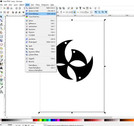
With the image still selected, a pop-up window should appear. We will adjust a few settings to ensure we get a good trace of our design. We will keep the "Live Preview" checkbox in the lower right selected to ensure we don't introduce any significant issues while adjusting the trace settings.
Since we are working from a pure black and white image, we will leave the "Brightness Cutoff" radio button selected. Setting the brightness cutoff threshold somewhere between 0.550 and 0.999 usually works well. Keep an eye on the preview image as you adjust this setting to ensure you don't push the setting too far. Click the "OK" button to proceed once the threshold is dialed in.

We should now have a vector image generated from our original raster image. Inkscape will have both versions (vector and raster images) displayed, with the vector image displayed on top. At this point, we can select the raster image and delete it, leaving just the traced vector image.

Now we will save our file out as a DXF. Select "File" and "Save As" from the top menu. From the file extensions list, choose DXF.
Sometimes the exported DXF will contain errors that must be cleaned up before being uploaded and used for manufacturing. To check for this, open the DXF file we just exported in LibreCAD and look for errors. In our example, we can see some extra lines were drawn around the sharp internal corners of the design, as shown below.

We can remove the excess lines by first selecting them one by one. After they have been selected, go to the menu bar and choose "Modify" and then the "Explode" option. This option will separate the lines from the rest of our part and allow us to remove them. Select the extra lines again and then hit the delete key on your keyboard to remove them from the file.

Now that the issues have been resolved, save the file as an R12 DXF file using the same name.
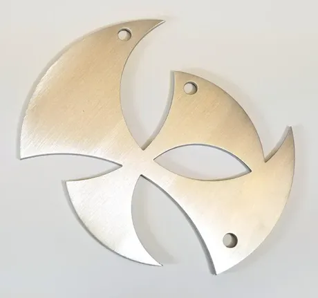
We now have a file that can be used for manufacturing. This design would be a great candidate for waterjet cutting or laser cutting. You can upload your DXF file to the Xometry Instant Quote Engine and choose from dozens of materials to get an instant price and lead time.

Once you are satisfied with your quote, you can proceed to checkout to order your custom parts. Below is a picture of how our part turned out.

Conclusion
In summary, we were able to go from an image to a real part by following these general guidelines:
- Prepare our source image in GIMP by boosting the contrast and converting it to a 1-bit black and white image.
- Use Inkscape's tracing function to generate a rough DXF from our prepared source image.
- Clean up our DXF using LibreCAD.
- Uploading our final DXF to the Xometry Instant Quoting Engine and ordering our part.