White Paper: Determining Which Manufacturing Process to Use to Achieve Highly Repeatable Parts

How do you make identical parts? This white paper discusses tolerances and repeatability, and how the two vary across manufacturing processes due to build set-up, material, and part design factors. It discusses the optimizations that manufacturers make to compensate for variation, and provides engineers with considerations for which process to use when creating parts for functional prototypes, assembly, or production.


Introduction to Repeatability
When scaling up parts for production, the default expectation for end-customers is that parts of the same design will have consistent dimensions and features across each unit. In other words, production methods should provide interchangeable parts from batch to batch. This is true, to a degree. Every manufacturer operates within a certain range of repeatability, which is how identical one part looks to another part of the same design and specifications. Repeatability is both qualitative and quantitative. The former being visual checks for inconsistencies in manufacturing or coloration, and the latter being the measurements of the produced parts to their expected tolerance range.
Does It Need to be Repeatable Right Now?
A quick note before jumping in: before determining what materials and manufacturing processes to use, consider what stage of the development process your project is at. When working with early prototypes, the level of repeatability is less important. In fact, the whole point of prototyping is to iterate through different designs. In this case, a manufacturer’s default tolerances in any process will result in parts that are accurate enough to CAD to show proof of concept. The rest of this paper will primarily look at precision tolerances and repeatability for functional prototypes, parts that assemble, and production-ready parts.
Achieving Repeatability Based on Process and Material
When seeking a certain level of repeatability, material and manufacturing process are the two most important factors. It’s important to note that process is typically the first consideration, since different manufacturing processes handle materials differently. For example, using the same material in two different machines, such as ABS in a 3D printer and ABS in an injection mold, will produce different surface textures, density, and part performance. However, for designers who are still uncertain about which material they need for their parts.
Here’s a tip: solid metal parts are rigid and can hold tighter tolerances than plastics, meaning more precise repeatability. However, the flexibility of plastic can be an advantage when assembling, even with looser tolerances than metals, by being pliable enough for snap tabs and other mating features.
Metal parts are manufactured with processes like CNC machining, sheet metal fabrication, or metal 3D printing. Traditional manufacturing methods like CNC machining or sheet metal can cut or shape metal stock extremely precisely. CNC machining has a standard tolerance of +/- 0.005” and sheet metal has a standard tolerance of +/- 0.005” – +/- 0.030” depending on the number of bends. Both of these can be customized for tighter tolerances through the use of special tooling, fixturing, and machine optimization.
Metal 3D printed parts typically have the same tolerances as 3D printed plastics. Direct metal laser sintered (DMLS) parts will achieve about the same level of precision as stereolithography (SLA), selective laser sintering (SLS), fused deposition modeling (FDM), PolyJet, Carbon (DLS), and HP Multi Jet Fusion (MJF) parts. Generally, 3D printed materials achieve tolerances of +/- 0.004” - 0.012” for the first inch and increases +/- 0.002” for every inch.
| Process | General Distance Tolerances |
|---|---|
Process CNC Machining | General Distance Tolerances For features of size (length, width, height, diameter) and location (position, concentricity, symmetry) +/- 0.005.” |
Process Sheet Metal Fabrication | General Distance Tolerances +/- 0.005” to +/- 0.030” depending on feature-to-feature locations over single planes or multiple bends. |
Process Fused Deposition Modeling | General Distance Tolerances +/- 0.004” for the first inch is typical, plus +/- 0.002” for every inch thereafter. Z Plane: +/- 0.010” for the first inch is typical, plus +/- 0.002” for every inch thereafter. |
Process Selective Laser Sintering | General Distance Tolerances +/- 0.005” for the first inch is typical, plus +/- 0.002” for every inch thereafter. |
Process Stereolithography | General Distance Tolerances +/- 0.005” for the first inch, plus +/- 0.002” for every inch thereafter. Z plane: +/- 0.010” for the first inch, plus +/- 0.002” for every inch thereafter. |
Process HP Multi Jet Fusion | General Distance Tolerances +/- 0.012" or +/0.003" per inch, whichever is greater, is typical. |
Process Injection Molding | General Distance Tolerances Mold cavity tolerances are +/- 0.005" when machining the mold and an additional +/- 0.002" per inch when calculating for shrink rate. |
How Tolerances Change Across Processes
Within each manufacturing process, various factors affect how identical, or repeatable, parts are from build to build. These determine the tolerance ranges of each process.
Factors that Affect 3D Printing Tolerances
3D printing typically builds parts by fusing materials together on a layer-by-layer basis to make the final shape. Manufacturers achieve precise repeatability by tuning build setup and process parameters. CAD modification can also help improve the product outcome.
| Factor | Description | Example |
|---|---|---|
Factor Materials | Description Some materials warp more easily than others. Warping can occur as the manufactured part cools after production, or if there are internal stresses in the raw materials that are strong enough to distort the part. | Example Nylon tends to warp or twist whereas polycarbonate is more rigid and stable for large or broad parts. Material conditions like age, the percentage of recycled material, and moisture content can also affect the outcomes. |
Factor Temperature | Description Temperature differences in a build can cause changes in the printed result. | Example Additional parts on a build plate can cause the temperature to rise and fewer parts on the build plate can cause the temperature to fall. These thermal changes can soften edges and lead to parts that measure slightly different from build to build. |
Factor Build Density | Description The number of parts in the build and their unique shapes, can affect the outcomes of their neighbors. | Example In processes like selective laser sintering (SLS), densely packed parts can hold and distribute extra heat to the build area. This can affect how much material fuses causing thicker edges as well as part stress during cooling that could cause deflection. |
Factor Geometry | Description Similar to the principles behind temperature and build density, parts with thicker cross-sections will hold heat longer in those areas than thinner geometries. This could cause deflection or deviation in shrink rates from standard prints. | Example Thick cross sections in SLS will cause the fusion time on those specific layers to increase which can cause slight increases in part thickness due to high heat exposure. |
Factor Orientation and Supports | Description Because 3D printing builds parts layer by layer, the orientation of a part in the build can significantly affect its outcome. Most 3D printing processes require support structures which are sacrificial features to allow for the creation of overhanging geometries during the 3D print. This can affect the surface finish or tolerances of that area compared to features produced without support structures. | Example Typically parts are oriented to minimize support or reduce thick cross-sections to create a standard print time per layer. Supported areas in processes like stereolithography (SLA) or direct metal laser sintering (DMLS) will require manual support structure removal and leave a grid of small protrusions where supports were attached. |
How Manufacturers Achieve Consistent 3D Printing Tolerances
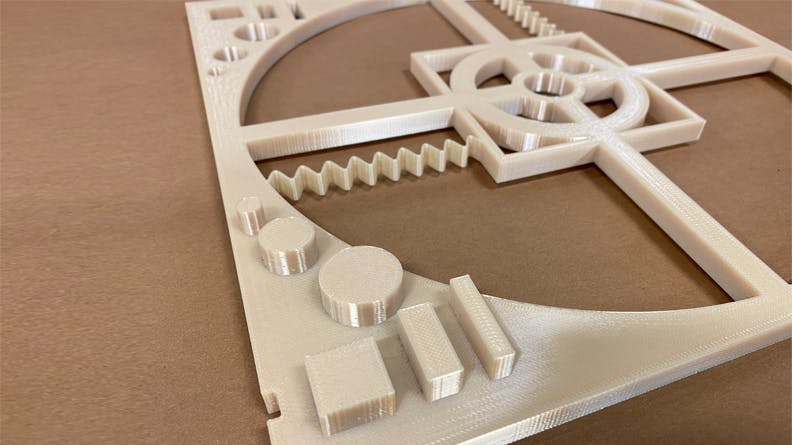
This is not to say that 3D printed parts are wildly unreliable. Before manufacturers even plan your part in a build, they calibrate machines to assure they can produce parts that meet specified CAD dimensions. Standard operating procedures for standardizing and calibrating industrial additive manufacturing machines include scale and offset calibration, where a 3D printing technician will build test parts, measure the results, and input the results into the machine to build preparation software. This software adjusts the scale and the edge offsets of the parts to better fit the CAD to the print.
Fused deposition modeling part used for machine calibration
Another standard 3D printing calibration procedure is to set up thermal controls. This can include heated build chambers, part beds, and sensors. For example, industrial 3D printing platforms like SLS or HP MJF use sensors to automatically track and heat specific zones to help even out thermal imbalances.
A final standard that manufacturers use to regulate 3D printing tolerances is the careful storage and handling of materials. Raw materials are typically stored in a dry, dark place to prevent moisture absorption, exposure to UV light, and oxidation that can degrade their performance and ability to fuse.
Bottom Line: Should You Use 3D Printing to Achieve Repeatable Parts?
When it comes to using 3D printing, a professionally calibrated printer will achieve an accurate net shape of the part within general tolerances and can do so over dozens and even hundreds of parts. But compared to traditional manufacturing processes, more factors affect standard 3D printing tolerances and standard tolerances are generally higher. Additionally, since each 3D printing process builds parts differently, CAD designs must be calibrated to the specific process to achieve critical dimensions. Ultimately, 3D printing is a good option for scaling up parts that need less strict tolerances, but be sure to specify part orientation and any critical features in your notes section to ensure each part is the same as the next.
Factors that Affect CNC Machining Tolerances
Generally, CNC machining has much higher repeatability than 3D printing because the machinist maintains tight control of the features being produced. The machinist uses coordinate-based g-code to program machines before every job, and machines can be stopped for in-process inspection to verify the part is meeting specifications.
However, like 3D printing, there are factors that can affect the tolerances of CNC machining parts.
| Factor | Description | Example |
|---|---|---|
Factor Machine Set-up | Description If the set-up has to be recreated at a different time on a different machine, parts may vary. | Example A part may be created as a prototype on a 3-axis machine. When the part is re-ordered at a larger quantity for production, and those parts are created on a more efficient 5-axis machine, this introduces different tool paths and will slightly change the part’s cosmetic appearance. |
Factor Tool Wear | Description Tool wear, or cutting tools that are less sharp, can cause slight variation on part features. | Example Linear irregularities on a part’s surface could indicate tool wear, as well as dimensional irregularities found during in process inspection. |
Factor Manual Finishing | Description Manual processes such as bead blasting, coating, and installing inserts may introduce variation due to different blasting grits, coating thicknesses, or the like. | Example A machinist may leave a “thumb print” when holding a part while bead blasting and their thumb masks a portion of the surface. Standards and best practices in finishing help mitigate these differences, as well as using the same supplier for post-machined finishes. |
How Manufacturers Achieve Consistent CNC Machining Tolerances
Manufacturers can prevent tolerance variation across parts through various ways. Tool wear is often discovered during a machinist’s regular part sampling and measuring, and are easily replaced if there is significant enough wear to cause deviation out of customer specifications.
To mitigate cosmetic and measurement deviations, engineers can communicate the acceptable level of variation with drawings and notes. A customer’s chosen machining inspection plan, such as ASQC Z1.4 2008 Level II with zero rejects, can help a manufacturer understand the acceptable tolerance limits. Xometry offers complementary standard inspections as well as advanced options depending on the job requirements.
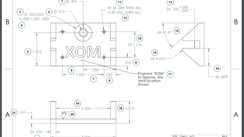
A drawing for a CNC machined part can ensure the manufacturer has all the information they need to create an in-tolerance part over various runs.
Bottom Line: Should You Use CNC Machining to Achieve Repeatable Parts?
When it comes to CNC machining, it’s likely that your parts will have less tolerance variation than 3D printed parts. Parts will likely function and look almost identically due to less variability in the upfront machining process and the ability to specify highly sophisticated inspection options. All things considered, CNC machining is a great option if a project requires very high precision, low tolerances, and high consistency across parts of the same design.
Factors That Can Affect the Tolerances of Injection Molded Parts
When it comes to repeatability, injection molding is a leader. This is because injection molding melts down pelletized material and injects it into a mold (also called a molding tool). The mold ejects the part and then repeats again and again until you have hundreds or thousands of identical parts. This molding tool is typically made of metal and is perfected via multiple iterations of cutting and tuning. Once you have the final tool, it can make parts with extremely high levels of precision of +/- 0.004” or better. This process is so repeatable that even miniscule details, like the grain or pattern on the metal tool, will show in the exact same place each time on the part.
Like 3D printing and CNC machining, various factors can affect the tolerances of injection molding parts.
| Factor | Description | Example |
|---|---|---|
Factor Machine Set-up | Description An injection molding run uses the same tool tuned to specific machine parameters such as the size of the shot of molten plastic going into the mold, the tool clamping force, and the material feed section’s temperature. These are all part of the tool “bio” that all must be specified for that part’s machine parameters and kept the same if the part production ceases and is started again at another time. | Example Both shot size and injection pressure will affect how features resolve in molding parts. For example, low pressure can result in a short shot, meaning not enough material is injected into the mold, resulting in incomplete features. Part of production’s setup is doing a “shot study” to test different parameters until the desired result is achieved and used for the remainder of the run. |
Factor Manual Processes | Description Injection molding can incorporate manual processes like hand loaded inserts or manually trimming runners off of gates. There may be slight deviations on those features from part to part. | Example For most low-volume production runs, the runner requires manual removal. Typically this is done with hand tools. In higher volume production, this can be mitigated by moving to a hot-runner gate that eliminates the need for manual trimming. |
Factor Tool Wear | Description A tool that molds abrasive materials can leave wear on a feature of the tool. This can typically be found around the gate area where the material is injected at very high pressure. | Example Prototype molds made of aluminum are softer and more prone to wear with abrasive materials such as glass-filled nylon. Production molds are made in much harder materials which mitigates this issue. |
Factor Material Condition | Description Material condition, from pellet uniformity to humidity level, can affect how it behaves when melted and injected into the part cavity. | Example Many plastics will naturally absorb moisture in the air. If pelletized material is not dried prior to molding, the molded part will have high humidity. This can cause visible streaks in the part or even affect the overall part fill. Drying the stock material before molding can prevent this variation. |
How Manufacturers Achieve Consistent Injection Molding Tolerances
If the tool is newly created, it is validated with production run samples, otherwise known as T1 shots. A tool is approved after it can create 10 good parts from a mold. When the machine is reset for subsequent runs, it is common to hold one of the original samples, using the same tool bio, as a template to check against the new batch. Additionally, since a single injection molding run may thousands of parts, each part of that batch is almost guaranteed to look identical.
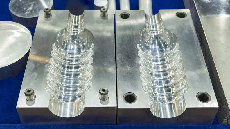
An injection molding tool. This tool is made out of CNC machining, then tested with T1 samples to perfect the part geometry.
Bottom Line: Should You Use Injection Molding to Achieve Repeatable Parts?
Overall, injection molding remains the most repeatable manufacturing process. The upfront communication and cost investment that goes into a mold tool can often be worthwhile if you need an extremely repeatable process for a large set of parts. Most consumer products, from your keyboard to your dashboard are all injection molded, meaning that everything works, fits, and can be easily manufactured at scale.
The Recipe for Creating Highly Identical Custom Parts
Ultimately, achieving repeatability can be boiled down to a few key concepts. Every manufacturing process has intricacies that requires specialized tuning and calibration. Once the manufacturer has tuned the machine to achieve standard tolerances, the engineer must communicate critical features and optimize the design of parts for a specific manufacturing process. In general, the most repeatable and precise process is injection molding, followed by CNC machining and then 3D printing. The best process for a part will then depend on where it lives in the development process, followed by the part’s application and required materials.
On-demand manufacturers like Xometry are prepared to customize parts to your needs at every stage of development. The best way to take advantage of the customization options is by learning how manufacturing processes compare, not only in terms of repeatability, but in terms of materials, feature resolution, cost, lead time, and more. Xometry provides free design guides and other resources to help engineers design parts that look and perform exactly to specification, every time.