Engineers who work with us here at Xometry use many different impact tests to learn a material’s characteristics, one of which is the IZOD impact test. There are various methods of determining how a material will respond or react; for the IZOD, you’ll need a pendulum and vises.
Here’s more about this test, its important factors, and how it compares to other impact tests (like the Charpy impact test).
What Is the IZOD Test?
The IZOD test is a way of determining the impact resistance of a material, specifically how much load it can handle before it breaks. This will help you choose the right material for your needs. Also called the notched IZOD test, it’s been accepted as a standardized method of doing so by the American Society for Testing and Materials (ASTM) and the International Organization for Standardization (IOS)—although the latter requires a slightly longer and wider piece of material for testing.
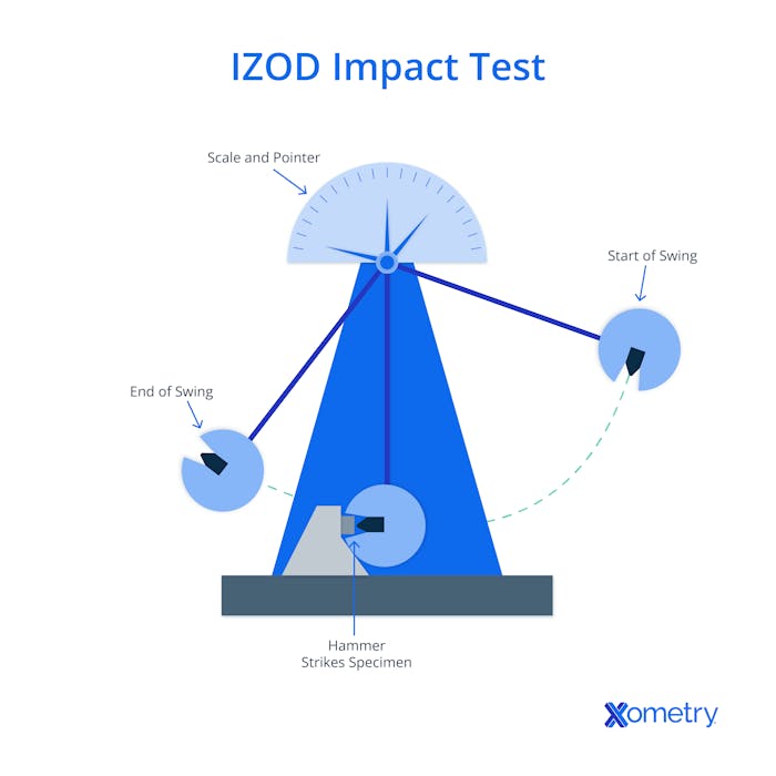
You can use it to test almost any material, but it’s most popularly relied on for plastics and polymers. You need a few different supplies and tools for conducting the test, including a rectangular sample of your material with a notch in it, a pendulum impact test tool, and a vise. Below is a diagram from the Xometry team of how the test works.

In addition to impact, the IZOD test also provides an idea of the amount of energy the material can absorb. All of this is imperative to know before these materials are then turned into products or structures that people use every day, such as bridges. When you’re using the IZOD to test, the method is ASTM D256 and for metals it’s the ASTM E23.
How to Conduct the IZOD Test & Calculate the Value
The IZOD test is relatively simple to do, but it does require specific conditions and measurements. Here are the general steps you can expect:
- First, prepare the test specimen, cutting it to the dimensions that the ASTM or IOS calls for and notching a 45-degree V-shaped section. The pendulum will hit right above this to break the material. You’ll want to have a vertex that sits at the midpoint of the length of the test material.
- Then, add the test material to the pendulum testing apparatus, at the bottom where the pendulum will swing and make contact. Secure it with the vise.
- You’ll set the height of the pendulum’s hammer (the standard is 24 inches) and note the potential energy the pendulum will have at this height. Then, release the pendulum.
- After the first test, you can increase the weight of the pendulum’s hammer until it breaks the material, which would then signify that the impact strength value can be calculated.
- If you need to do an IZOD test in cold temperatures, the test material will be placed in a freezer until it reaches equilibrium, and then taken out and tested.
- To get the impact value, you’ll divide the impact energy by the thickness of the specimen. This number will have a unit of J/m or ft-lb/in, which translates to the amount of kinetic energy that’s needed to deform and break the material.
Factors That Affect the IZOD Impact Test
There are a few details that make a difference in the impact strength reading you get from a material:
1. Yield Strength
Although a material may be heat-treated to have higher yield strength, heat treating processes can also decrease the matertial’s ductility. This can lead to a lower impact strength overall.
2. Ductility
Materials with higher ductility tend to deform before they’re permanently broken or damaged. Since this is the case, you’ll find these materials tend to have higher impact strengths.
3. Notches
It’s important to get the notch tip radius and notch depth right in order to get an accurate reading of impact strength. This is because the notch localizes the stress and the sensitivity will vary depending on what material you’re using.
4. Temperature and Strain Rate
A lower temperature will influence how brittle a material is and how much strain happens during the test. The cooler it gets, the more likely the material’s strain rate decreases, which is important to be aware of.
5. Fracture Mechanism
You’ll want to understand what kind of fracture is at play, which will come down to the makeup and structure of the material you’re testing. It’ll either be a ductile or brittle fracture, or feature characteristics of both these types. Different kinds of cracks will result, including cleavage and microvoid coalescence.
IZOD Test vs. The Charpy Test
Both tests use the same type of swinging pendulum device, but the IZOD is normally used for testing plastics, whereas the Charpy is popular for testing metals. We’ve covered a few other differences between these tests in the table below.
| Feature | IZOD | Charpy |
|---|---|---|
Feature Specimen Orientation | IZOD The material sits vertically and fixed at one end forming a cantilever | Charpy The material sits horizontally is supported on both ends |
Feature Point of Contact | IZOD The weight strikes the test material above the notch | Charpy The weight strikes directly behind the test material’s notch |
Feature Notch Direction | IZOD The notch faces the weighted hammer | Charpy The notch faces away from the weighted hammer |
Feature Specimen Dimensions | IZOD 2.5” (L) x 0.5” (W) x 0.125” (T) | Charpy 2.16” (L) x 0.39” (W) x 0.39” (T) |
IZOD Test vs. The Charpy Test
How Xometry Can Help
Whether you’re testing plastics or metals, we have various services here at Xometry that cater to both these types of materials. You can get instant quotes for plastic 3D printing, sheet metal fabrication, plastic injection molding, and metal extrusion on our website.
Check out our Technical Datasheet Glossary to learn more about different material properties.
Disclaimer
The content appearing on this webpage is for informational purposes only. Xometry makes no representation or warranty of any kind, be it expressed or implied, as to the accuracy, completeness, or validity of the information. Any performance parameters, geometric tolerances, specific design features, quality and types of materials, or processes should not be inferred to represent what will be delivered by third-party suppliers or manufacturers through Xometry’s network. Buyers seeking quotes for parts are responsible for defining the specific requirements for those parts. Please refer to our terms and conditions for more information.


