What is a Bevel (Beveling)?
A bevel is a sloped/angled surface following an edge. It is formed by cutting or grinding the material at an angle other than 90°. It involves removing material from the edge to create a gradual slope or chamfer. This process introduces a consistent face that blends the meeting of faces. The resulting beveled edge can have a wide range of angles and face widths, depending on the specifics of the application and functional requirements.
Bevels are applied in almost all areas of product design and manufacture for diverse functional and aesthetic benefits. They can be found in applications such as architectural details, furniture, automotive components, machine parts, blades, and tools.
In engineering, bevels are used to modify the shape or configuration of a material or component to achieve specific functions or meet design requirements. They serve various functional purposes in engineering applications including dissipating stress by removing sharp corners or edges and creating additional clearance for other parts, allowing for proper fit, movement, or clearance in mechanical systems. Bevels also serve in engineering products for aesthetic and safety purposes. Relieving sharp edges can make a product look better engineered and seem like it was the subject of greater care. Removal of sharps has obvious safety benefits, too.
The importance of beveling in manufacturing is that it helps facilitate the fitting of components by both easing and forcing alignment as tapered surfaces engage. Bevels of various formats play a role in welding processes, too. A beveled edge provides a groove or channel or controlled shape, increasing penetration and fusion of the weld filler material into the joined parts. Additionally, in machine components such as shafts or fasteners, beveled edges can reduce stress concentrations to improve fatigue resistance and the overall strength of the components.
Types of Bevel (Beveling)
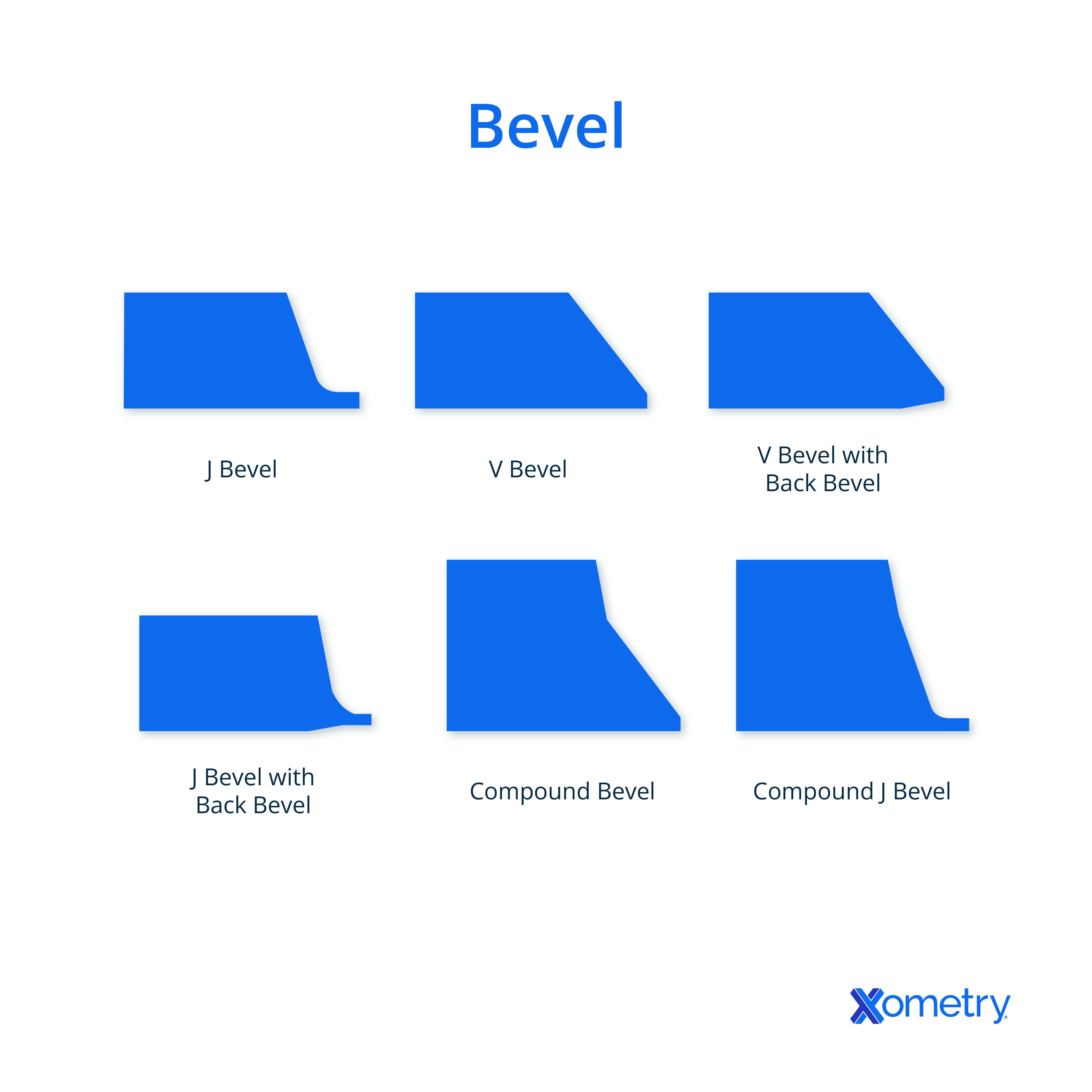
There are several types of bevels as seen in Figure 1 below:

1. Plain Bevel
A plain bevel describes an edge that is cut or shaped at a constant angle relative to the meeting surfaces and of generally constant width along its entire length. Plain bevels are extensively used in diverse applications for both functional and aesthetic purposes. For example, plain bevels can significantly ease the assembly or insertion of components by integrating self-location into assembly processes. Stress concentrations, spalling, and wear can be reduced by removing sharp corners or edges. This results from stresses being more evenly distributed onto the connected surfaces, minimizing the risk of cracks or edge-induced damage during assembly and operation.
Plain bevels can enhance the appearance of a part by adding visual refinement. They provide a finished and deliberate look to edges or surfaces. In many contexts, in particular, in tools or equipment whose utility involves unprotected human handling, a plain bevel can be used to remove sharpness and create a safer, blunted edge.
2. J-Prep Bevel
A J-prep (or J-groove) bevel is a particular example of a beveled edge joint preparation that is extensively used in more advanced and demanding welding applications. It is named "J-prep" because of its resemblance to the letter "J" in cross-section. A J-prep bevel is typically used for butt welds, where two materials or components are joined along a straight (or cylindrical) seam. The J-prep is beveled on one or both sides of the joint, while the other side may be left perpendicular to the joint line.
The J-prep bevel delivers some significant benefits in welding applications in higher value and higher failure risk manufacture. Some benefits include: providing an increased surface area for the weld, resulting in enhanced weld strength and integrity, facilitating deeper penetration of the weld formation into the joint ensuring greater and more comprehensive fusion between two or more parts, and enabling better access for visual inspection and quality control during the welding process and an easier assessment of completion after welding.
J-prep bevels are used in most heavy industries, including pressure vessels, reactor cores, critical infrastructure construction, shipbuilding, piping, and structural fabrication.
3. J-Prep with Back Bevel
A J-prep (or J-groove) with a back bevel differs from a standard J-prep only in that a simple angled bevel is applied to either the J-prep part or as a deeper feature on the second part to be jointed, to compliment the J-prep on the first part. The second or back bevel, is an additional bevel applied to one or both parts that improves penetration and access. The back bevel creates a slope or chamfer on the J-prep, opening the welding path with the additional bevel configuration.
The J-prep with a back bevel offers certain advantages in welding applications. Firstly, the combination of the J-prep and back bevel creates a larger weld volume compared to a simple J-prep bevel. The increased weld volume improves joint strength, weld penetration, and load-bearing capacity. The J-prep with a back bevel also allows the operator (or programmer in an automated system) greater control over the weld profile, allowing greater optimization of the weld bead shape and dimensions. Finally, The back bevel allows for better access to monitor the welding process and inspect the quality of the weld.
J-prep with back bevels are commonly used in the same industries as basic J-prep welds. The additional cost implicit in the secondary bevel process, however, is only worthwhile in higher value applications or ones in which inspection (and failure) in use carries a cost burden.
4. Compound Bevel
A compound bevel preparation details a beveled periphery or surface junction that is blended with two complimentary angled surfaces on each edge. They are used in various and unrelated applications, particularly in woodworking, machining metal components, and particularly for the visual appeal they create.
For example, in woodworking, these features are used in joinery on more advanced mitered corners or complex craftsman joints. They can create cleaner and more tight-fitting connections with better aesthetic qualities between wood components. In metal machining processes, compound bevels are occasionally utilized to create complex shapes, blending parts into tapered edges and curved surfaces, or forming attractive or technically advantageous compound angles on metal components.
5. Compound J-Prep with Back Bevel
A compound J-prep with a back bevel delineates an additionally complex form of joint preparation in welding applications. This combines the features of a J-prep bevel and a back bevel with multiple angles and slopes. Either on the J-prep bevel, on the obverse side of the joint from the J-prep, or on both edges, there is included a compound back bevel with two progressive bevels applied. This combination results in a compound joint profile with multiple angles and slopes.
The combination of the J-prep and back bevel provides a yet larger weld volume, in comparison to the simpler forms of J-prep bevel. This improves joint strength and load-bearing capacity. The multiple bevels of the compound joint configuration allow for even deeper penetration of the welding material. The compound J-prep with back bevel also allows for better control over the weld profile, enabling skilled welders to impose a desired weld bead shape and dimensions. Finally, the compound joint configuration can assist in distributing stress more evenly along the joint and outwards into the substrates, minimizing the risk of failure or stress cracking.
Compound J-prep with back beveling is most applicable where enduring weld joints in stressed conditions are crucial and often life-critical. The system is widely used where lifetime inspection opportunities are difficult. Examples are reactor systems (chemical and nuclear), pressure vessels, critical infrastructure fabrication, shipbuilding, piping, and heavy machinery manufacturing.
How Does a Bevel Compare to a Fillet or a Chamfer?
Bevels, fillets, and chamfers are the range of edge treatments used in diverse applications. While they are closely related, they offer distinct characteristics and serve divergent purposes. A bevel is a sloping or angled surface (or sequence of surfaces). It is created by cutting or shaping an internal or external corner at an intermediate angle that generally (but not necessarily) halves the natural meeting angle of the faces that form the corner. Bevels are often used to remove sharp edges, facilitate assembly, improve weld penetration/access, and provide a desired aesthetic. To learn more, see our guide on Fillet vs. Chamfer.
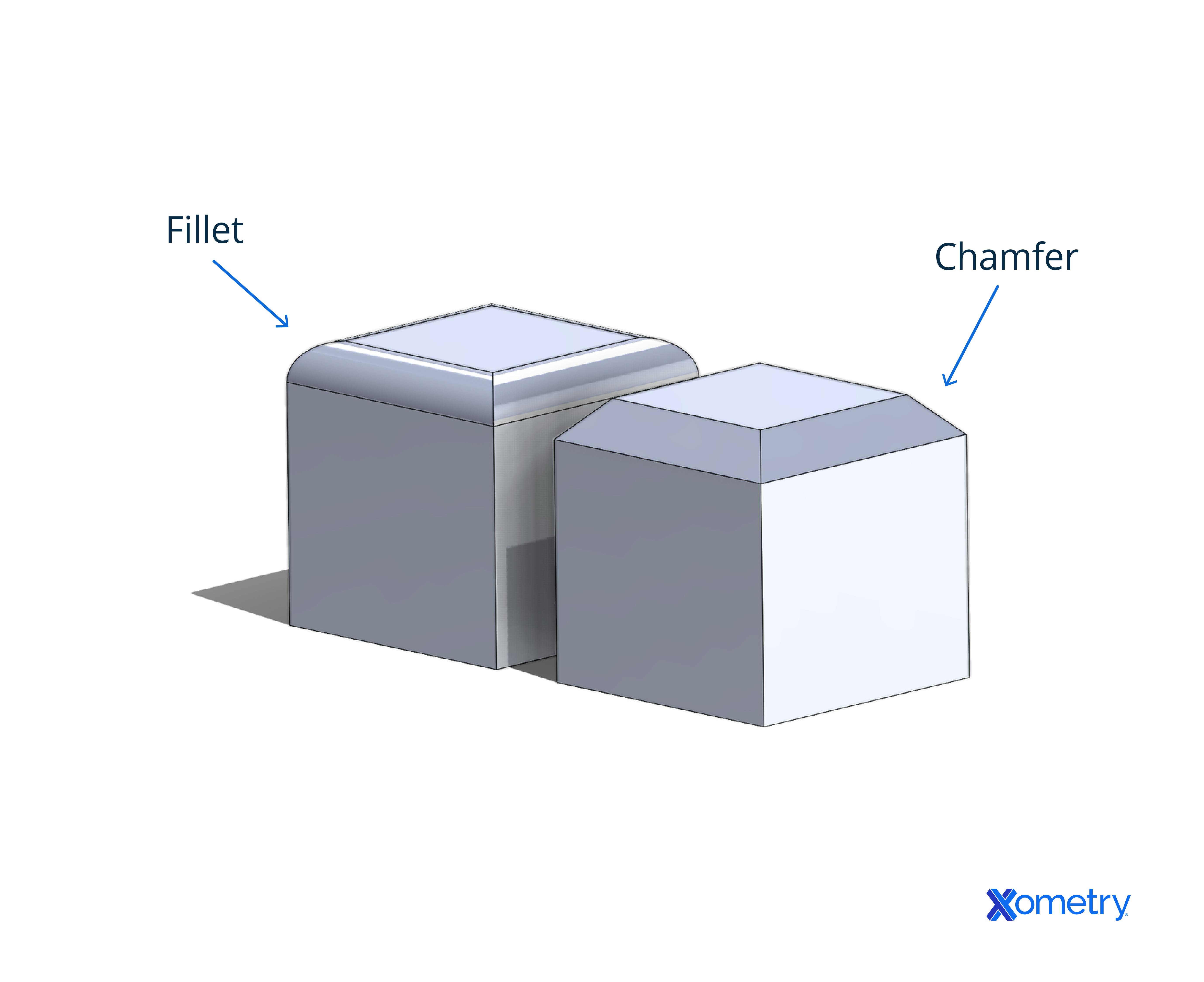
A fillet, on the other hand, is a rounded, convex, or concave transition between two surfaces, generally (but not always) tangential to the two surfaces. They are typically formed by adding a constant radius curvature to a corner or edge, creating a smooth transition between two faces. Fillets are used to reduce stress concentrations, improve strength, and enhance aesthetics. They eliminate sharp corners, reduce external corner fragility, and distribute stresses more evenly in internal corners. Fillets can be found in virtually all products encompassing welded joints, machined parts, moldings, furniture edges, and architectural details. Figure 2 is an example of a fillet and a chamfer:

Fillet and chamfer examples
A chamfer is an alternative and less specific term for a beveled edge or surface. It is formed by cutting or shaping the material at an angle, usually bisecting the connected faces (45 degrees for 90° junctions) unless made asymmetric for particular reasons that suit the context. They are typically straight cuts or bevels made at a specified angle along an edge or corner. Chamfers are used to remove sharp edges, facilitate assembly, provide a decorative appearance, and prevent damage to fragile or worn exposed corners. Chamfers can be found on furniture edges, machined parts, architectural features, and bolt heads. Figure 3 above depicts a chamfer.
Advantages of Using Bevels in Your Engineering Designs
Bevels bring context-sensitive advantages when incorporated into engineering designs. Listed below are some of the advantages:
- Reduce stress in components, eliminating sharp corners or edges that are otherwise prone to wear and damage.
- Ease the assembly of components, allowing easier insertion and alignment of parts.
- Facilitates deeper penetration, and ensures better fusion and a stronger junction through improved weld quality and strength.
- Influences the strength and functional/cosmetic durability of components.
- Lends an air of craftsmanship and completion to part designs.
- Eliminates sharpness, reducing the risk of injuries and other-object damage from sliding contact and pinch.
- Beveled edges are of particular significance in injection molded components in consumer products, at the mating edges where two parts meet. To correct the flash and irregularity, it is common to “bury” the part line by using a beveled edge on the two mating parts. This makes the junction line a crisp and machined feature, rather than a pair of imperfect part lines.
Disadvantages of Using Bevels in Your Engineering Designs
There are some disadvantages that can apply to their inclusion in a part design/manufacture. These disadvantages are applicable on a case-by-case basis and are listed below:
- Can result in a loss of material and, in some narrow cases, reduced strength or structural integrity.
- Adds additional steps to the manufacturing, fabrication, or finishing processes, requiring specialized tools, equipment, and often skilled labor.
- Such features may not be suitable or feasible for all design requirements, where sharp corners or 90-degree angles are necessary for functional or aesthetic reasons.
- While beveled edges can facilitate assembly, there can be instances in which bevels interfere with easy assembly by encouraging misalignment, requiring additional care and precision to ensure mating.
The Role of Beveling in Improving the Performance and Efficiency of Gear Systems
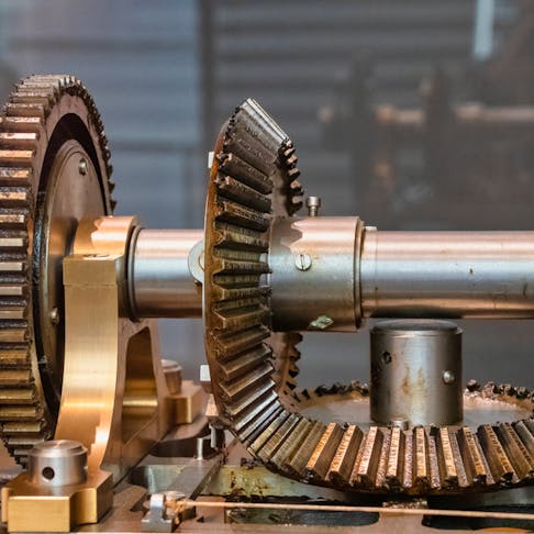
Beveling plays a significant role in improving the engagement and efficiency of non-parallel and disengaging gear systems. Some of these are listed below:
- The beveled tooth profile for drive connection of intersecting shafts allows for precise meshing and engagement, minimizing friction and power losses during operation.
- Optimized tooth contact provided by beveling helps to distribute loads evenly. This also minimizes noise and vibration that can arise from misalignment or uneven contact between gear teeth.
- Bevel gears can handle higher loads and transmit greater torque between unaligned shafts. Furthermore, if the gear teeth are curved they will provide a larger contact area and more gradual tooth engagement.
- Better gear engagement and disengagement result from the beveling of selectable parallel shaft spur and helical-cut gears.
- Lower wear at the gear edges and lower gearbox oil contamination result from corner beveling of both permanently engaged and layshaft selectable spur and helical gears.
Summary
Xometry provides a wide range of manufacturing capabilities including CNC machining, 3D printing, injection molding, laser cutting, and sheet metal fabrication. Get your instant quote today.
Disclaimer
The content appearing on this webpage is for informational purposes only. Xometry makes no representation or warranty of any kind, be it expressed or implied, as to the accuracy, completeness, or validity of the information. Any performance parameters, geometric tolerances, specific design features, quality and types of materials, or processes should not be inferred to represent what will be delivered by third-party suppliers or manufacturers through Xometry’s network. Buyers seeking quotes for parts are responsible for defining the specific requirements for those parts. Please refer to our terms and conditions for more information.


