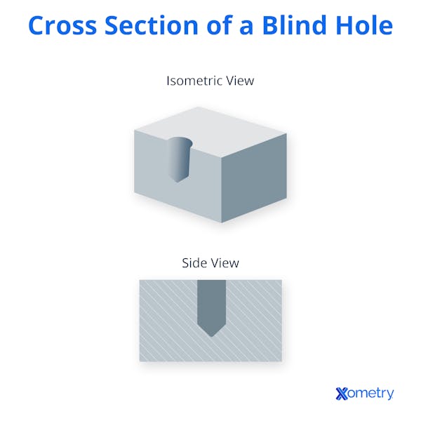
A blind hole is a hole that does not pass completely through a part, meaning it terminates before reaching the opposite surface, regardless of the fraction of total thickness. The depth of a blind hole depends on its function: for threaded holes, it is determined by the required thread engagement and tap clearance; for unthreaded holes, by the intended fit or feature geometry.
This article will describe what blind holes are, how to drill and tap them, and what callout to use when indicating a blind hole on a drawing. Other types of holes are listed here for comparison.
How To Drill a Blind Hole
The hole depth must be determined by the optimal thread engagement of the fastener being used, plus an additional depth to allow the tap to thread to the correct depth. A blind hole can be drilled in many different ways. A hand drill can be used, but maintaining perpendicularity and consistent depth with it is difficult. A piece of tape wrapped around the drill bit can serve as a depth indicator. Alternatively, some hand drills have a depth indicator that extends from the front of the drill to physically stop the drill from going too deep.
A drill press is a more suitable tool for drilling blind holes than a hand drill. It can maintain perpendicularity and consistent depth better, but accuracy still depends on setup and bit alignment.
CNC machines and lathes can produce the most accurate blind holes. On a lathe, the drill is typically mounted in the tailstock or tool turret, while the rotating workpiece feeds into it. This method produces the most accurate holes. If precise holes are required, then the hole can be slightly undersized, and a reamer can be used to finish the hole.
Regardless of the method used for drilling a blind hole, it is important to ensure that cutting fluid is supplied to the drill and that chips are evacuated continuously. This is usually done by backing the drill out of the material every so often to carry the chips out of the hole. Failure to do this can damage the drill or even get it stuck in the hole and break it.

Choosing the Right Tap for a Blind Hole
Blind holes can be tapped manually or on a CNC machine. Every thread size has a companion drill size that must be used. For example, an M10 bolt would require an 8.8 mm drill bit to allow the tap sufficient material to cut a full thread into the hole. Bottoming taps with a flat bottom are best suited to blind holes. There are many drill tap tables available online that indicate the hole to be drilled for a corresponding thread size.
As with drilling, it is important to evacuate chips during tapping, as taps can very easily break if chips aren’t removed. It is also important to keep the tap perfectly aligned with the hole’s central axis. Alternatively, a roll tap can be used to eliminate the chip problem. Roll taps cold form the threads, pressing them into the hold walls instead of cutting them.
How To Clean Blind Holes
When drilling blind holes, it is important to clean out the chips, as these can cause a range of problems, like increased drill wear and drill breakage. During drilling, a high-pressure stream of liquid coolant or air can be used to blow the chips out of the hole. The drill flutes will not be able to efficiently remove chips if the hole becomes too deep. After drilling, the holes must be cleaned again to remove any leftover debris. In this case, a hand-operated air gun can be used. For best results, a specialized hand-held hole cleaner can be used to simultaneously blow compressed air into the hole and suck the blown-out debris into an enclosed container.
Drill Depth Clearance in Blind Holes
When drilling blind holes for tapping it is important to drill to the correct depth to allow the tap to have enough space to cut or form the required number of threads. This ensures that the fastener has enough thread engagement for maximum holding strength while also having enough clearance beyond this for the tap. The hole depth will depend on the type of tap used. For example, a taper tap will need a deeper hole than a bottom tap or spiral flute tap for the same number of threads as it has a longer point and lead-in before it is able to cut a full-depth thread, these taps are also better suited to hand tapping. The formulas shown below can be used as general guidelines:
For holes with a depth twice the diameter of the fastener, the tap depth should be:
Thread Depth + (Thread Pitch * 9)
For other holes the tap depth should be:
(Thread Depth + (1 + Thread Pitch * 4)) + (Thread Pitch * 5)
What Is the Callout Symbol for a Blind Hole?
The callout symbol for a blind hole is typically represented by a circle with a perpendicular line at the center extending halfway into the circle, indicating the depth of the blind hole. This symbol communicates to machinists that the hole does not go all the way through the material, requiring special drilling or tapping procedures.
Choosing the Right Tap for a Blind Hole
Blind holes can be tapped manually or on a CNC machine. Every thread size has a companion drill size that must be used. For example, an M10 × 1.5 thread typically requires an 8.5 mm drill bit for a standard 75% thread engagement. Bottoming taps with a flat bottom are best suited to blind holes. Drill tap tables are widely available and list the correct drill size for each thread specification.
During tapping, chips must be cleared frequently to prevent tap breakage. It is also important to keep the tap perfectly aligned with the hole’s central axis. Alternatively, a roll tap can be used to eliminate the chip problem. Roll taps (form taps) cold-form threads by plastically deforming the hole walls instead of cutting material away.
How To Clean Blind Holes
When drilling blind holes, it is important to clean out the chips, as these can cause a range of problems, like increased drill wear and drill breakage. During drilling, coolant or compressed air can help flush chips from the hole, but excessive pressure can drive debris deeper and should be used cautiously. The drill flutes will not be able to efficiently remove chips if the hole becomes too deep. After drilling, the holes must be cleaned again to remove any leftover debris. In this case, a hand-operated air gun can be used. For best results, a specialized hand-held hole cleaner can be used to simultaneously blow compressed air into the hole and suck the blown-out debris into an enclosed container.
Drill Depth Clearance in Blind Holes
When drilling blind holes for tapping, it is important to drill to the correct depth to allow the tap enough space to cut or form the required number of threads. This ensures that the fastener has enough thread engagement for maximum holding strength while also having enough clearance beyond this for the tap. The hole depth will depend on the type of tap used. For example, a taper tap will need a deeper hole than a bottoming or spiral-flute tap for the same number of threads because it has a longer lead before cutting a full-depth thread. These taps are also better suited to hand tapping. There are no formal formulas for calculating tap depth in blind holes, but machinists often follow general shop guidelines. A common rule of thumb is to provide enough thread engagement for strength and add roughly one to one and a half times the thread pitch as clearance beyond the last full thread.
What Is the Callout Symbol for a Blind Hole?
There is no dedicated or standardized symbol that graphically represents a blind hole. Instead, blind holes are indicated in technical drawings through dimension callouts specifying thread size and depth, often accompanied by the word “BLIND” or a depth value following the hole notation. This notation informs machinists that the hole does not go all the way through the material and requires specific drilling or tapping procedures.
An example such as “M20 × 2.5 – 25” specifies a metric thread of 20 mm nominal diameter with a 2.5 mm pitch and a 25 mm depth. If two depths are given (e.g., “M20 × 2.5 – 15 ↧25”), the first refers to the thread depth and the second to the total hole depth.
Blind Hole vs. Through-Hole
A through-hole extends completely through the material, while a blind hole stops partway through the thickness.
Both blind and through holes can be threaded or left plain, depending on their function. Blind holes are often tapped using bottoming or spiral-flute taps, while through holes can use taper or plug taps. Blind holes pose a higher risk of tap breakage because chip evacuation is more difficult.
What Are Other Types of Holes Used in Machining?
Different applications may require different hole types. The holes listed below can be through holes or blind holes:
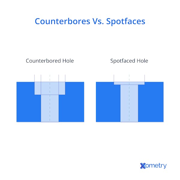
- Counterbore: A counterbore is a standard hole with a larger, flat-bottomed recess above it. This hole has a flat bottom so that a socket cap fastener will not stick out above the surface of the part.
- Spotface: A spotface hole is essentially a shallow counterbore hole used to provide a flat mating surface between the underside of the fastener and the material being joined that is perpendicular to the hole’s central axis.

- Countersunk: A countersunk hole is similar to a counterbore hole, but has a conical hole above the standard hole. A flat-head socket screw is used in these types of holes.
- Counterdrill: A counterdrill is a combination of a counterbore and a countersink. The top of the hole is counterbored, and then it transitions into a countersink leading to the pilot hole. These holes are sometimes called counterdrills in workshop contexts, though the term is not standardized.
- Taper: A tapered hole gradually narrows along its depth and may either terminate internally or pass through the part. Such holes are commonly used for tapered pins, pipe threads, or Morse tapers.
For more information, see our guide on Types of Holes in Engineering.
Summary
This article presented blind holes, explained them, and discussed their various applications. To learn more about blind holes, contact a Xometry representative.
Xometry provides a wide range of manufacturing capabilities, including CNC machining and other value-added services for all of your prototyping and production needs. Visit our website to learn more or to request a free, no-obligation quote.
Disclaimer
The content appearing on this webpage is for informational purposes only. Xometry makes no representation or warranty of any kind, be it expressed or implied, as to the accuracy, completeness, or validity of the information. Any performance parameters, geometric tolerances, specific design features, quality and types of materials, or processes should not be inferred to represent what will be delivered by third-party suppliers or manufacturers through Xometry’s network. Buyers seeking quotes for parts are responsible for defining the specific requirements for those parts. Please refer to our terms and conditions for more information.


