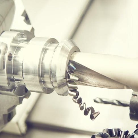
What is a hole in engineering? What are the primary types of holes? This article will answer those questions and more. Below I'll provide an overview of twelve types of holes in engineering: the blind hole, through hole, interrupted hole, simple hole, counterbole hole, spotface hole, countersink hole, counterdrill hole, tapered hole, screw clearane hole, tapped hole, and threaded hole.
1. Blind Hole
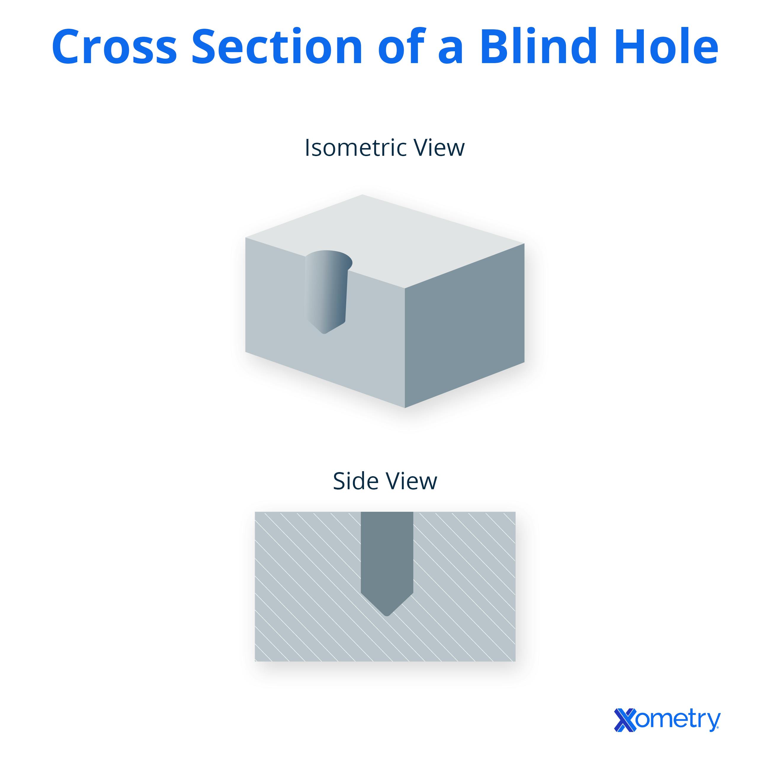
A blind hole is a hole that does not go completely through the material. This type has been reamed, drilled, or milled to a specified depth without going through to the workpiece’s other side.
There isn’t a callout symbol for blind holes. A blind hole is specified with a diameter and a depth specification or the remaining amount of the workpiece.
Blind holes are used in engineering to measure residual stresses. CNC milling machines are used to make blind holes by running a thread milling cycle. There are three methods of threading blind holes: conventional tapping, single-point threading, and helical interpolation.
2. Through Hole
A through hole is a hole made to go completely through the material. A through hole goes all the way through the workpiece. It is sometimes called a thru-hole. The callout symbol used for a through hole is the diameter ‘Ø’ symbol. Through holes are shown on engineering drawings by stating the hole’s diameter and depth. For example, a 10-diameter hole that goes straight through the component would be represented as “Ø10 Through.” Through holes are used for a variety of purposes in engineering. For example, through holes are often used for electronic components, such as holes drilled in printed circuit boards (PCBs).
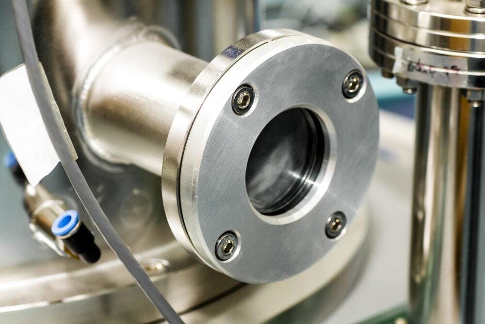
This component has both blind and through holes.
Image Credit: Shutterstock.com/Rattanapon Ninlapoom
3. Interrupted Hole
As the name suggests, an interrupted hole is a hole where another feature intersects the hole. A new hole-making operation drills a sequence of coaxial holes with gaps in the workpiece (the material is interrupted by empty space). Each drilling cycle is made of cutting and non-cutting moves.
4. Simple Hole
A simple hole in engineering refers to a circle that has been cut out of an object. There are different kinds. The symbol used for a simple hole is ‘Ø.’ Simple holes are revealed on engineering drawings by giving the diameter and the specific depth of the hole. Simple holes serve many various purposes in engineering, from creating holes for fasteners to connect to, to creating parts.
FREE CNC Machining Design Guide
5. Counterbore Holes
A counterbore hole is a simple hole with a broader hole above and connected to it. It is a standard screw hole. The callout symbol for counterbored holes is ‘⌴’. The diameter symbol and depth number is also added. Counterbored holes are often used for PCBs. This type of hole is used in machining operations for socket-head screws. Counterbore holes are used for applications where the bolt or screw must sit beneath the surface.
6. Spotface Holes
A spotface hole is similar to a counterbole hole, but is shallow. It allows a fastener to sit flat. The callout symbol for a spotface hole is the counterbore symbol of ‘⌴’ with the letters ‘SF’ inside it Spotfaces are used in engineering to create a smooth, flat surface on a machined part. A part made through casting may not have a smooth and flat surface like a machined component.
This means a spotface hole is machined, guaranteeing that the part being connected to a component with a rough exterior is located correctly.
7. Countersink Holes
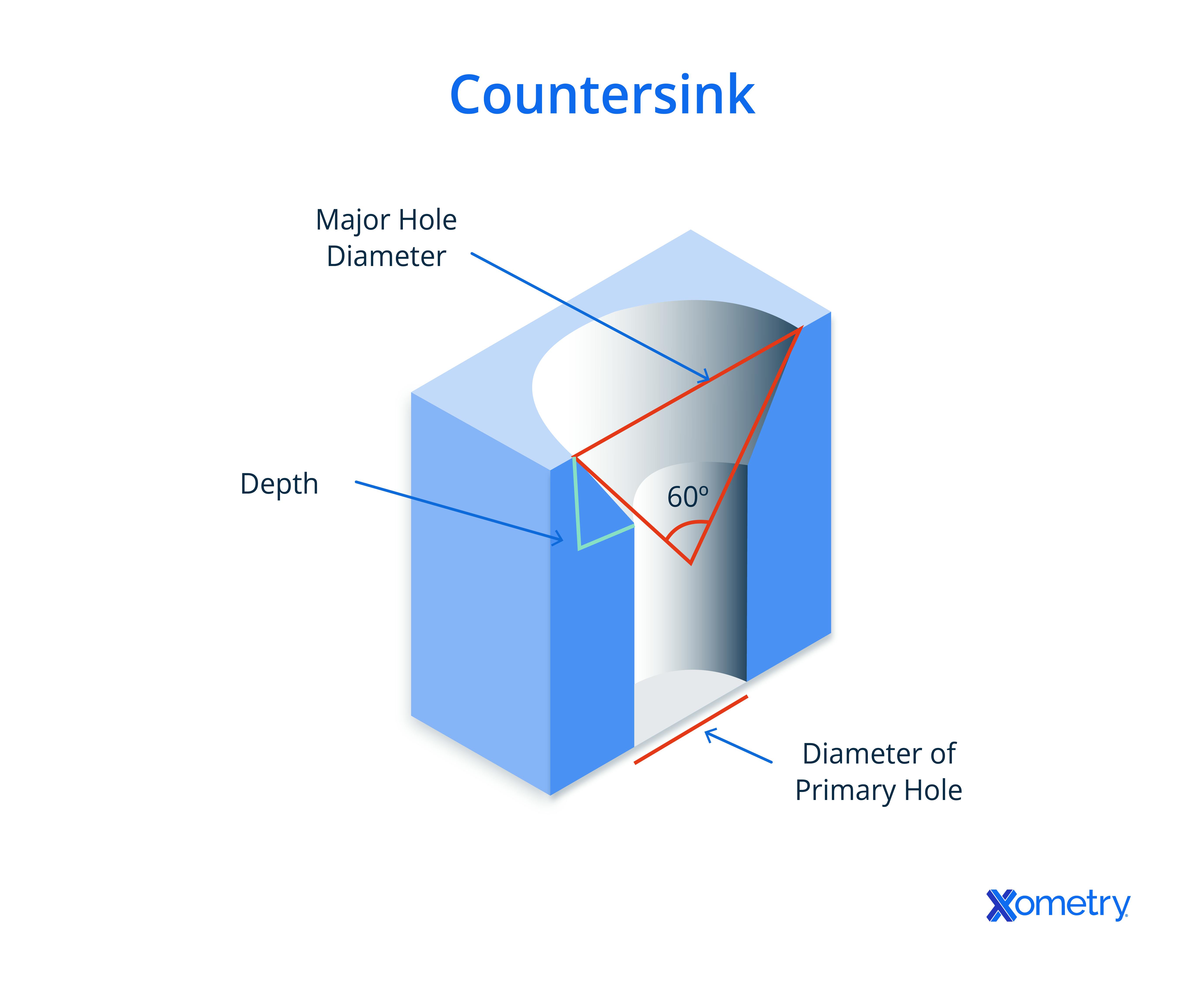
As opposed to a counterbore hole, a countersink hole has a more conical shape. A countersunk hole is a simple hole with a conical hole above it. Drilling this cone-shaped hole requires a little more calculation and precision than drilling a counterbore hole. The callout symbol for a countersink hole is ‘⌵’. Countersunk holes are used in engineering when a countersunk bolt or screw is required. Countersink holes like counterbore holes allow a bolt or screw to sit below the surface.
8. Counterdrill Holes
A counterdrilled hole is similar to a countersink hole, but has a recess above it. The callout symbol for a counterdrill hole is the same as a countersink hole, ’⌵’ but with a depth listed. Counterdrill holes, like countersunk holes, are used in engineering when a counter sunk bolt or screw is needed. In addition, they are often used for PCBs.
9. Tapered Holes
A tapered hole is when the start diameter of the hole is a different width than the end diameter of the hole. It is wider at one end than the other. The callout symbol for a tapered hole is a triangle with a line through it. The end diameter and ratio are also listed. Tapered holes are used in engineering for many different applications. One common example is to secure cutting tools or other tool holders.
10. Screw Clearance Holes
A screw clearance hole is a simple hole with a slightly bigger diameter than a screw thread so that the screw can pass through. It allows an object large enough to enable threads of a screw or bolt to pass through but not the head of the screw or bolt being used. The callout symbol for a screw clearance hole is the same as a simple hole and has the specified depth. The size of a screw clearance hole is calculated by adding the diameter of the screw and the diameter of the screw head and then dividing the sum by two. This method of selecting the size will yield the largest hole that will fit under the head of the fastener. Many CNC milling machines can create a screw clearance hole. Screw clearance holes are used in engineering for parts that need a screw or bolt to go through them.
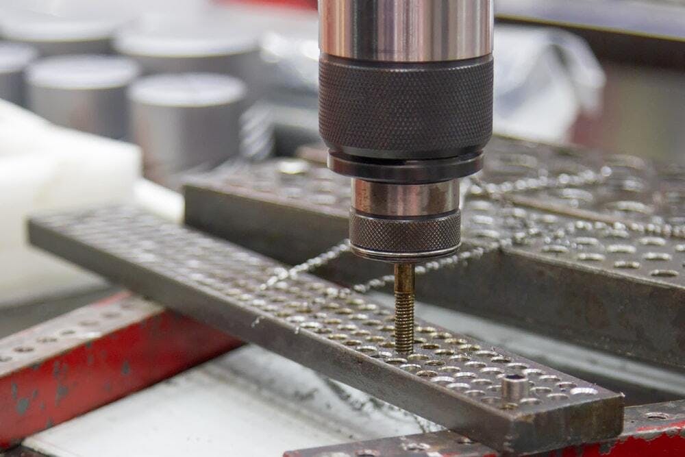
A drill point making a tapped hole
Image Credit: Shutterstock.com/Chok Chokchai
11. Tapped Holes
A tapped hole is a hole drilled before a machine screw is inserted. It has threads cut into the hole’s inside surface through the tapping process. They are used in engineering with metals where a nut and bolt cannot be used. They hold threaded components with their internal threads. The callout symbol for a tapped hole, for metric holes, has the diameter symbol replaced with an ‘M’. For different thread types, such as a Unified National Fine (UNF) thread, the numerical dimension is shown first, then the thread type is listed as “UNF”. Tapped and threaded holes are similar but made by two different machining processes. The difference between threading and tapping is the tool used and the surface on which the processes happen. The threading process creates threads outside of a hole with a die tool. The tapping process makes threads inside a drilled hole with a tapping tool.
12. Threaded Holes
Threaded holes are holes with threads. They are similar to tapped holes but are made differently.
In engineering, threaded holes are integral aspects of mechanically fastened parts. They are easy to add with CNC machines. Threads are usually added last after most other elements of the part have been machined. For more information see our Guide on Threaded Holes.
The callout symbol for threaded holes is the ‘Ø’ diameter symbol, unless they are metic, in which case the diameter symbol is replaced with an ‘M’. The threaded depth is written. The difference between threading and tapping is the tool used for hole making and the surface on which the processes happen. The threading process creates threads outside with a die tool. The tapping process makes threads inside a drilled hole with a tapping tool.
For more information see our Guide on Threaded Holes vs. Tapped Holes.
Xometry provides a wide range of manufacturing capabilities including CNC machining, 3D printing, injection molding, laser cutting, and sheet metal fabrication. Get your instant quote today.
Disclaimer
The content appearing on this webpage is for informational purposes only. Xometry makes no representation or warranty of any kind, be it expressed or implied, as to the accuracy, completeness, or validity of the information. Any performance parameters, geometric tolerances, specific design features, quality and types of materials, or processes should not be inferred to represent what will be delivered by third-party suppliers or manufacturers through Xometry’s network. Buyers seeking quotes for parts are responsible for defining the specific requirements for those parts. Please refer to our terms and conditions for more information.


