Threaded Holes: An Introduction and Guidelines
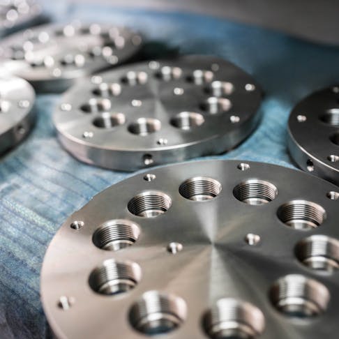
Threaded holes are integral aspects of mechanically fastened parts. They are easy to add with CNC machines. Threads are usually added last after most other aspects of the part have been machined. Getting it wrong and being forced to scrap a part can be a very costly mistake. There are several factors designers and machinists must consider when they approach threaded components. Careful planning along with the following guidelines will make the addition of threaded holes go smoothly.

1. Making Threaded Holes: Cutting and Forming
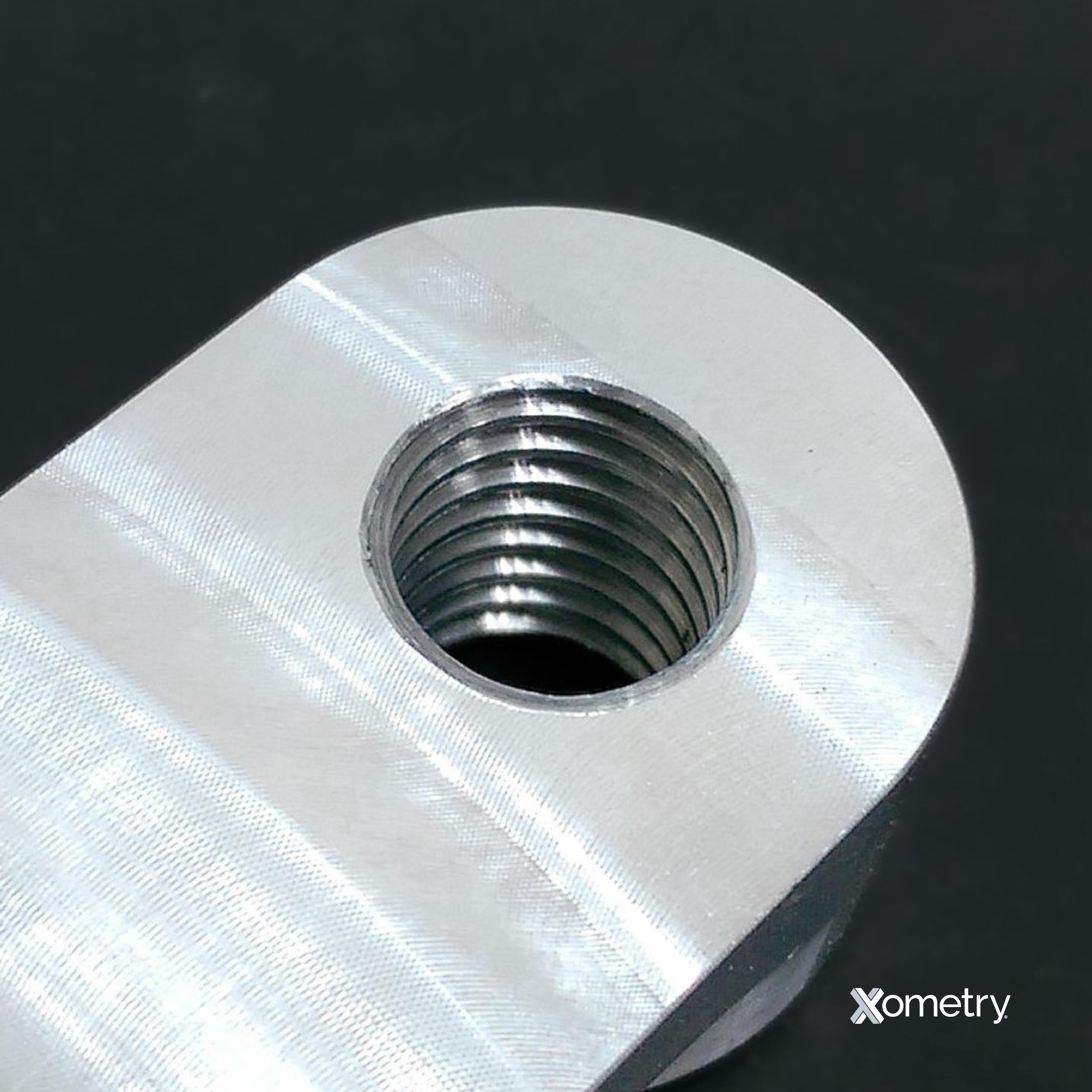
The internal thread in a threaded hole can be either cut using a cutting tool (a cutting tap or single lip cutting tool) or formed using a forming tap. Though both methods will yield the same result, the following factors must be considered before choosing a method:
- The hardness of the part’s material
- The size of the threaded hole
- Whether it is a blind or through-hole
- Access to suitable machinery.
Use a traditional cutting or forming tap for threaded holes up to M6 and a single lip cutting tool for threaded holes larger than M6. The larger taps will require more machine horsepower.
Use a cutting tap when adding a threaded hole to hard material. The fluting of a cutting tap gives metal shavings enough space to escape and also provides a path for coolant or lubricant to flow down to the cutting edge.
Use a forming tap when working with soft, non-ferrous metals like aluminum, brass, copper, or lead, or materials that do not form chips when drilling (but instead form long ribbons). Beware that a forming tap tends to distort the entry hole (and exit hole for through holes) due to the forces associated with displacing material.

2. Keep It Standard
Keeping to established standards will negate the need for specialized tooling, reduce machining time, and save money. If there is an off-the-shelf solution, that’s almost always the best option to use. This means sticking with thread sizes that are common in your country and for which machine shops will most likely have tooling. However, do not compromise a design just to stick to a standard if a custom solution is the best option.
3. Correct Positioning for Threaded Holes
Ensure that the entire diameter of the threaded hole is contained within the part. Remember that the outer diameter of the thread will be larger than the pilot hole or internal thread diameter. If the threaded hole is too close to the part’s edge, the threading may break through the side of the part, ruining the surface finish, breaking the tap or cutting tool, or jeopardizing the part’s integrity.
Add a boss to the part if some extra thickness is needed to accommodate a threaded hole.
FREE CNC Machining Design Guide
4. Managing Angled Surfaces
Machining a threaded hole into an angled surface can be difficult.
If a threaded hole is added to an existing angled surface, first machine a pocket to create a flat surface from which a threaded hole can be added. Drilling and tapping on an angled surface will likely break a traditional tap — normal tooling isn’t designed for the asymmetrical bending stresses such tapping would incur.
If the angled surface does not yet exist, first add the threaded hole to the part and then machine the angled surface. Take care to ensure the threaded hole depth meets the design after the angled surface gets added.
5. Threaded Hole Types
There are two types of threaded holes: blind or through. Each demands specific considerations during the part’s design stage to ensure both that the threaded hole can be machined and that it does not interfere with other features.
- Blind Threaded Hole
A blind threaded hole does not go all the way through a part. Its bottom may end in a flat surface if the hole was created with an end mill, or in a cone, if it was made using a traditional drill. Use a bottoming tap if full threads need to extend to the bottom of a blind threaded hole.
A blind threaded hole’s notation on a 2D drawing must state the depths of both the drilled hole and the thread.
- Through Threaded Hole
A through threaded hole possesses both an entry and exit on opposing sides of the part or feature. The thickness of the part must be considered as the tap or cutting tool reach may not be enough to thread the entirety of a deep hole. If the tap or cutting tool reach is not enough to thread the hole from one side, consider one of the following options:
- Add threads as deep as the tap or cutting tool allows. Note that a portion of the hole may not have a thread.
- Add threads from both sides of the hole as deep as the tap or cutting tool allows. Note that the threads will not align where they meet.
- Add threads from both sides of the hole as deep as the tap or cutting tool allows. Note that the threads may not reach each other and that a portion of the hole will be unthreaded.
6. Deep Threaded Hole
A deep threaded hole is one in which the depth of the threading is more than 1.5x the diameter of the thread. Deep threaded holes present unique machining challenges. The increased tool-to-part contact time creates more heat and requires a greater cutting force, increasing the risk of tool breakage.
Pay attention to machining parameters and tap or cutting tool geometry. Consider reducing cutting speeds and feed rates to reduce the forces exerted on the tap or cutting tool. Choose a tap with larger flutes to remove chips quicker and allow more coolant or lubricant to reach the cutting edge.
For more information see our guide on Types of Holes in Engineering.
Threaded Holes vs. Tapped Holes: Difference and Comparison
A tapped hole is a hole drilled before a machine screw is inserted, and has threads cut into the hole’s inside exterior through the tapping process. A tapped hole is used in engineering with metals where a nut and bolt cannot be used. Tapped holes hold threaded components with their internal threads. Threaded holes are holes with threads, these threads are created using a die tool. Tapped and threaded holes are similar in that they both contain threads that can be used to fit fasteners. Tapped holds and threaded holes are different in that they are made with different machining processes. The difference between threading process and tapping process is the tool used and the surface on which the processes happen. The threading process creates threads outside of a hole with a die tool. The tapping process makes threads inside a drilled hole with a tapping tool.
For more detailed information, see our full Guide to Tapped Holes vs. Threaded Holes.
Getting Great Threaded Holes for Your Parts
Following these guidelines will help you design parts with threaded holes that can be easily machined. As your partner, Xometry will provide you with support and manufacturing capabilities to turn your design into reality. Contact a Xometry representative today for your machining needs.
