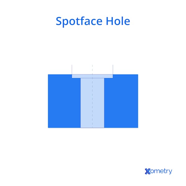
A spotface is a flat-faced, shallow cylindrical recess that is larger in diameter than the hole it is concentric with. It is cut to impose a flat landing surface for contacting/mating parts, such as washers or fastener heads. The primary reasons for spot-facing holes are:
- To provide a stable, flat surface for fasteners or washers on an otherwise rough or uneven part.
- To provide the same flat landing surface on an otherwise curved surface of a part.
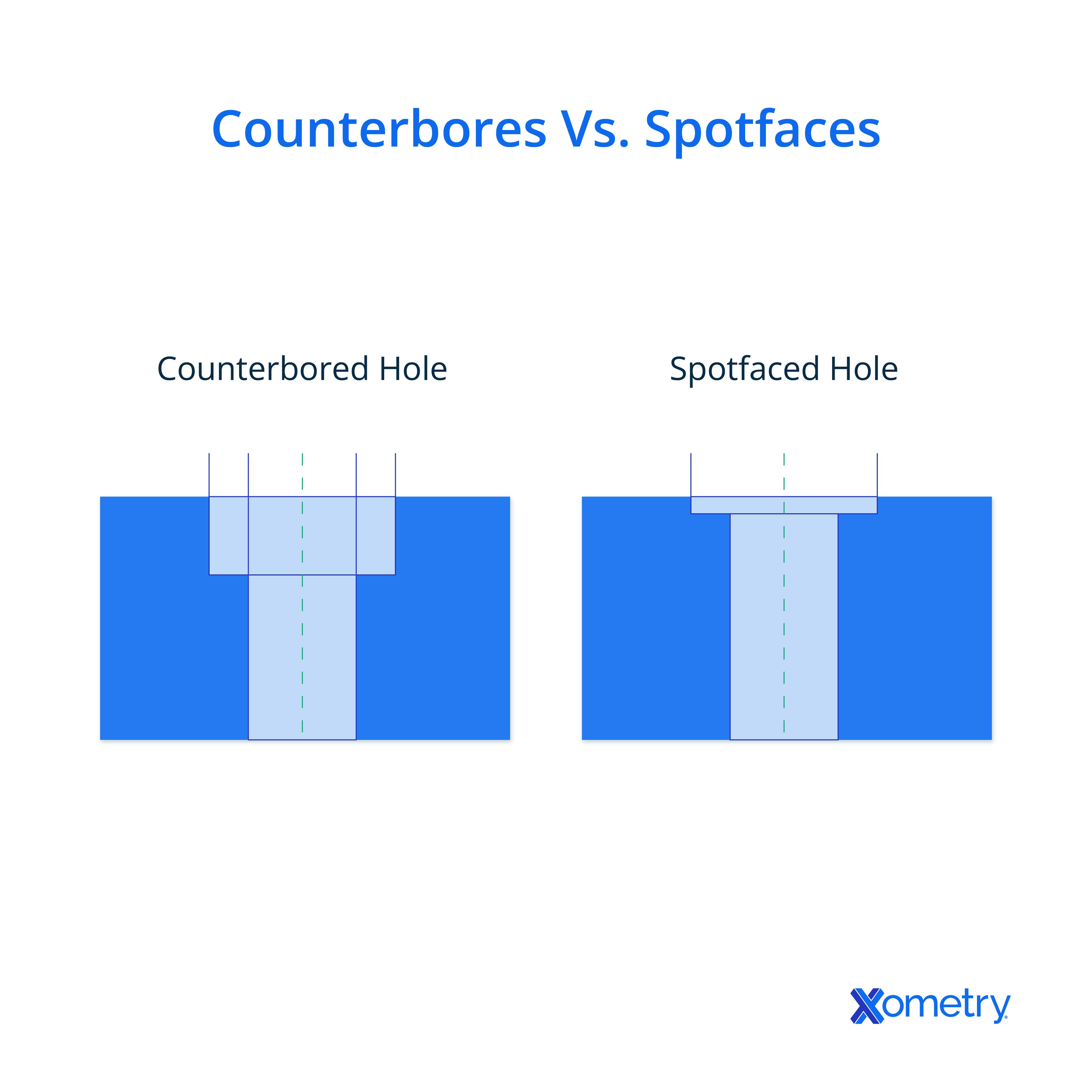
Spotfacing and counterboring use similar tooling, but a spotface is a shallow flat seat, while a counterbore is deeper to recess the fastener head. This article will further discuss spotface holes, how to drill one, how to choose the right tap, as well as the applications and uses of a spotface hole.

How To Drill a Spotface Hole
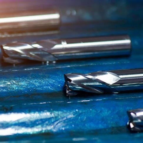
Spotfaces are often machined on mills or CNC, but piloted and reverse spotfacers are also used with hand-held tooling when needed. Piloted spotfacer or counterbore cutters are available, with a cylindrical pilot that fits into the drilled hole before cutting. However, spot-facing is more often performed on a mill or CNC machine.
Choosing the Right Tap for a Spotface Hole
Through holes are usually tapped with a plug (middle) tap, and a taper tap can also be used to start the threads, depending on the setup. These two forms of tap have chamfered leads that help start the thread smoothly, though centering depends on the pilot hole and guidance.
For a through hole, the choice between taper and plug (middle) taps depends on the depth of the hole to be tapped. There must be enough total length of unaltered tap and shank combined to allow the tap to penetrate deeply enough to complete the thread through the part.
Blind holes are typically started with a taper or plug (middle) tap and finished with a bottoming tap to reach full depth. The choice between taper and plug (middle) taps depends on the relationship between chamfer length and required thread depth. Use a plug tap when the taper’s lead would prevent full-depth threads.
In my work, a well-placed spotface is about more than appearance. It ensures components seat perfectly, even on challenging curved or rough surfaces.Audrius Zidonis, Principal Engineer at Zidonis EngineeringNote from the Editor
Applications and Uses of Spotface Holes
The purpose of spot-facing is to create a smooth, perpendicular surface for securing components. Such a component may be a post/standoff held down by a threaded fastener, or a fastener holding other parts on the reverse side of the spotface.
In either case, the spotface provides a flat seating area on a controlled and precise surface. It improves flatness and precision on otherwise uneven or curved parts.
Spotface Hole Size Charts
There is no single universal chart that governs spotface sizing across industries. Designers and machinists size the diameter and depth per application, and some organizations or fastener standards provide reference tables that may inform sizing.
In general, spot-facing is sized to be larger than the part that is designed to land upon it. It should have sufficient depth to ensure a fully annular flat surface, removing all curvature or roughness from the landing surface.
Some corporate manuals, such as Boeing’s BDM-1327, specify the nominal spotface diameter as the cutter size, defined as the flat seat diameter plus twice the cutter corner radius. ASME Y14.5-2009 defines the drawing callout for a spotface. The specified diameter refers to the flat seat size, and the standard does not include a universal allowance for tool radii.
What is the Callout Symbol of a Spotface Hole?
In ISO and ASME drafting, a spotface is indicated using the counterbore symbol with the letters SF placed inside or adjacent to it. This denotes that the machining is a shallow counterbore to provide a seating surface rather than to recess a fastener head.
The callout symbol for a spotface hole.
Spotface Holes vs. Counterbore Holes
Spotface holes are blind or through holes with a shallow, flat-bottomed recess cut into the surface. They provide a precise seating surface on otherwise rough or curved parts, without fully recessing the fastener head.
Counterbore holes create a cylindrical recess that allows a fastener head with a flat bearing surface to sit flush or below the surrounding material. They are commonly used with:
- Common drive types for threaded fasteners with flat undersides, including external hex, internal hex, Phillips, crosshead, Torx, pin Torx, and slot.
- Threaded fastener head styles with flat undersides, such as pan, button, cap, hex, and washer hex.
- Some non-threaded knock-down joint fasteners, such as quarter-turn locks and push nuts, can also use counterbored seats.
- Certain rivet types, such as pop, peened, and push rivets, may use a counterbored or spotfaced seat for proper installation.
To learn more, see our full guide on Spotface vs. Counterbore Holes.
Both types of holes are shown in the diagram below:

What Are the Other Main Types of Holes in Engineering?
The five other common types of holes used in engineering are:
- Through Hole: A hole of constant or stepped diameter that passes completely through a part.
- Blind Hole: A hole that does not pass completely through a part. The end profile depends on the tool used: twist drill (commonly 118° or 135° included angle), ball end mill (hemispherical tip), end mill (flat, square tip), Forstner bit (flat tip with center spur), or auger bit (flat tip with threaded center spur).
- Counterbore Hole: A flat-bottomed, cylindrical recess at the opening of a blind or through hole, sized to fit a specific fastener head type or to meet ANSI/ISO dimensional standards.
- Countersunk Hole: A conical cut at the outer face of a blind or through hole, whose diameter and angle are defined to fit a particular fastener head, or a family of fastener heads.
- Tapped Hole: A through or blind hole in which threads have been cut into the wall, either for its full depth or partially, to accept a mating fastener.
Summary
This article presented spotface holes, explained what they are, and discussed when to best drill this type of hole. To learn more about spotface holes, contact a Xometry representative.
Xometry provides a wide range of manufacturing capabilities, including CNC machining and other value-added services for all of your prototyping and production needs. Visit our website to learn more or to request a free, no-obligation quote.
Disclaimer
The content appearing on this webpage is for informational purposes only. Xometry makes no representation or warranty of any kind, be it expressed or implied, as to the accuracy, completeness, or validity of the information. Any performance parameters, geometric tolerances, specific design features, quality and types of materials, or processes should not be inferred to represent what will be delivered by third-party suppliers or manufacturers through Xometry’s network. Buyers seeking quotes for parts are responsible for defining the specific requirements for those parts. Please refer to our terms and conditions for more information.


