What is Nesting?
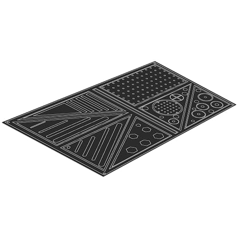
In the manufacturing industry, the term "nesting" refers to the process of laying out multiple parts on a single sheet. The nesting process reduces scrap waste and optimizes production for the manufacturer. In this article, we will explore some of the best practices for preparing and nesting your parts in a DXF file. If you have a nested file you're looking to quote, you can upload it straight to the Xometry Instant Quoting Engine, which natively supports DXF files, including ones that have nested parts!
Should You Nest Your Parts?
Before we go over the best practices, let's take a step back and ask ourselves if we should even make an effort to nest our parts. The answer to that question will depend primarily on where you are coming from. For instance, if you are a manufacturer, nesting files for sheet cutting is fairly standard and often necessary to get the most out of your available material and optimize production.
From a buyer's perspective looking to get parts made, it is important to remember that most sheet-cutting shops will already have the means and familiarity with nesting parts. In fact, in some cases, it can actually hinder the manufacturer by receiving an already nested file because it locks them into a pre-defined configuration that may be less than ideal. For example, many sheet part manufacturers work from material that has already had parts cut from it. It may require them to use a whole new piece of material instead of one they could have maximized the use of by nesting the parts themselves. The manufacturers are also more in tune with their material sizing, machine limitations, etc.
In short, it's sometimes easier for both parties if you submit your parts as individual files. The Xometry Instant Quoting Engine makes it simple to upload and order many individual parts, and our manufacturers can handle the nesting process during manufacturing! There are instances where it makes sense for a customer to nest their parts ahead of time, such as when the nested file will consume an entire sheet of material or when the customer is supplying their own material. We cover more of the advantages and considerations in our article about Nesting Files for Sheet Cutting.

Best Practices for Nesting Your Parts in a DXF
1.) Look for and fix common design errors
When submitting any design for manufacturing, it's always a good idea to look it over and clean up any errors. If your design file has problems, it can result in an unusable file which will cause slowdowns during manufacturing while the issues are troubleshot. Below is a checklist of the common issues you want to look for when getting your design file ready:
- Duplicate or overlapping lines, curves, points, etc.
- Title block information, notes, and dimensions were not removed.
- Open geometry (e.g., open curves, disconnected lines, etc.)
- Lines with lengths less than zero.
Tip: Export your parts as polylines to ensure your geometry has continuous, closed elements. Ensure non-profile elements such as text, titles, auxiliary lines, etc., are removed. Read more on best practices for preparing a DXF.
2.) Avoid using SPLINES
SPLINES are commonly used in CAD software to construct more complex geometry and shapes, such as the profiles of gears or sprockets. The issue is CNC equipment often runs from G-code and typically can only perform linear or circular movements. As a result, SPLINE features are approximated as lines and arcs, resulting in some loss of geometric accuracy.
Tip: Where possible, use lines and arcs in your design instead of SPLINES. During export, ensure your CAD software is not set to export splines and instead export as polylines.
3.) Space your parts appropriately
Some spacing is needed between parts to ensure your nested parts come out correctly. Without proper spacing, issues can occur, like poor edge quality, warping, or unwanted melting. Parts should also be spaced appropriately to account for kerf, also known as the width of the material being removed due to the cutting process. At the minimum we recommend spacing your parts 3-5x the kerf size. To ensure there is little to no risk of the aforementioned defects affecting your parts, we recommend a distance between cuts of 0.80" (20.3mm).
Typical kerf varies based on the process, but the following guidelines are useful:
- Laser Cutting kerf: 0.010"
- Waterjet Cutting kerf: 0.040"
- Plasma Cutting kerf: 0.150"*
*Xometry's sheet cutting services utilize laser and waterjet as primary platforms due to their higher detail accuracy.

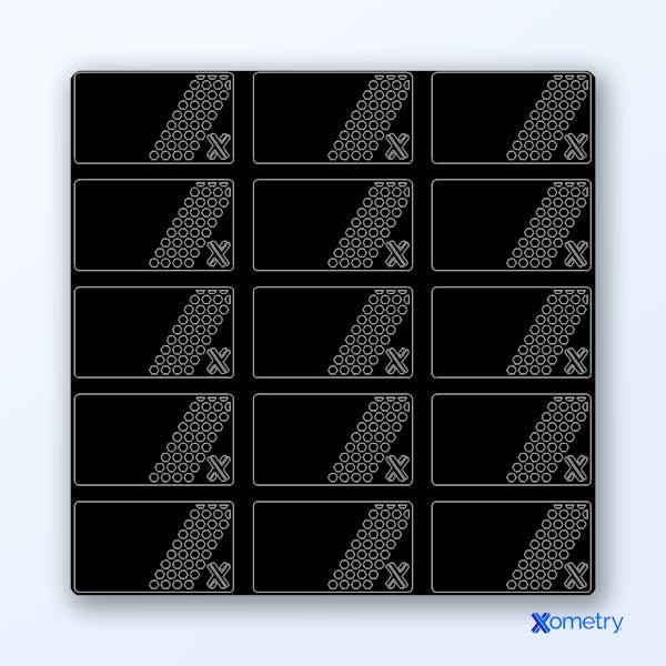
DXF file containing nested parts with appropriate spacing.
4.) Add break-away tabs for small parts
In cases where you have small parts or ones with delicate features, adding break-away tabs will help reduce loss and damage to the parts during manufacturing. Tabs can also be useful for instances where you want all the parts to remain on the sheet after cutting, such as when additional processing steps may be needed or when you are dealing with very thin material.
Tip: Add break-away tabs to parts smaller than 2" in size, or for features that are delicate. Tabs about 0.020" in size should work for most parts.
5.) Optimize with nesting software
Using automated nesting functions or dedicated software to optimize your part configurations can simplify the process. Automatic nesting software can help you squeeze the highest number of parts into the space available, reducing material waste. The software can also work around complex shapes that may otherwise be tricky to optimize manually. Make sure to export your file set as a DXF after nest optimization.
Tip: Some popular CAD software, such as Autodesk's Fusion, have nesting functions built-in natively or through extensions. Check to see if your software may already have an automatic nesting function built-in.
6.) Include a Bill of Materials (BOM)
Finally, after nesting all of your parts, be sure to include a BOM with your quote. This document gives our manufacturers a reference to ensure all pieces within the nested file are accounted for. This reduces the risk of your parts getting lost during packaging and shipping.
A BOM can be uploaded straight into the Xometry Instant Quoting Engine® along with your quote. Simply click “Configure Part” during quoting and upload the BOM under the “Drawings and Files” section. Uploading a BOM as an attached PDF file is preferred, but leaving written notes is also helpful to manufacturers. To add notes, simply scroll to the bottom of the part configuration screen.
Tip: Adding part markings to your DXF, such as engravings, can also be helpful in distinguishing parts from each other, especially ones with similar geometry!
Become an Expert in All things Sheet Metal Fab
Disclaimer
The content appearing on this webpage is for informational purposes only. Xometry makes no representation or warranty of any kind, be it expressed or implied, as to the accuracy, completeness, or validity of the information. Any performance parameters, geometric tolerances, specific design features, quality and types of materials, or processes should not be inferred to represent what will be delivered by third-party suppliers or manufacturers through Xometry’s network. Buyers seeking quotes for parts are responsible for defining the specific requirements for those parts. Please refer to our terms and conditions for more information.

