How to Start Designing with Common Sheet Metal Features in Autodesk Inventor
Sheet metal parts are manufactured by bending and deforming sheets of metal. With Autodesk Inventor software, you can create and edit digital prototypes of sheet metal components. In this article, learn about the fundamental sheet metal features in Autodesk Inventor and how to use each feature.


How to Use the Sheet Metal Face Feature in Inventor
The sheet metal face feature is one of the most common sheet metal features. While sheet metal faces are critical for building out sheet metal parts, they aren’t too complicated to form. All you need to start creating a face feature is a closed profile sketch. Then, follow these simple steps to make a face.
- Step 1: To start, click Start 2D Sketch on the XZ plane and choose a shape of the sheet metal face you want to create.
- Step 2: Next, choose a sheet metal default for the part and set the sheet metal rule.
- Step 3: With the closed profile sketch made and sheet metal rule created, launch the face command from the sheet metal ribbon or the right-click marking menu.
- Step 4: If there is only one closed profile in the sketch, Inventor automatically selects it and shows a preview in the graphics area. If there are multiple profiles, select the shape for the sheet metal face you would like to work on. To change direction or thickness, click a selection in the offset direction panel.
- Step 5: Finally, click OK to create the face or click apply to make more sheet metal faces.
Check out the SolidProfessor Autodesk Inventor Face tutorial for further information on sheet metal faces.
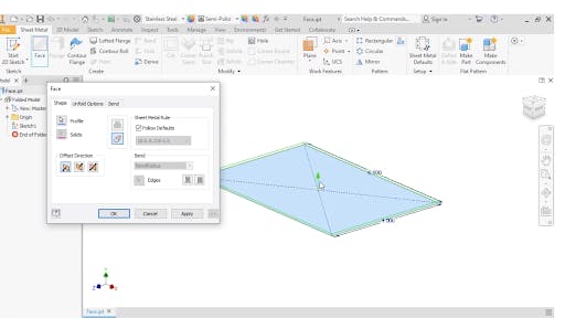
Sheet Metal Face Feature in Autodesk Inventor
How to Use the Sheet Metal Flange Feature
The second common sheet metal feature is called the Flange. The sheet metal flange feature consists of a face and bends connected to an existing face along a straight edge. To create one, select the Flange command and then pick the edge or edges you would like to add the Flange to.
- Step 1: To begin a Flange, click Flange in the sheet metal ribbon panel or right-click the graphics area and select the Flange icon.
- Step 2: The Flange dialogue block will appear with one edge selected, and a preview will appear of the Flange in the graphics area. Click on the sheet metal part to add more edges if needed or deselect any unwanted edges by holding down control+P while clicking the edge.
- Step 3: In the Flange dialogue box, you can set the feature's size and position using the parameters. You can also select the direction and height as well as the Flange Angle and Bend Radius to suit your design in this dialogue box better.
- Step 4: Finally, click OK to close the fladge dialogue box or click Apply to create more Sheet Metal Flange Features.
To learn more about this feature, click the full Autodesk Inventor Sheet Metal Flange video.
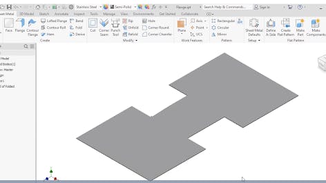
Sheet Metal Flange Feature in Autodesk Inventor
Become an Expert in All things Sheet Metal Fab
How to Use the Contour Flange Feature
In Inventor, the Contour Flange is a command used to create a sheet metal flange from an open profile sketch. It can be accessed using the sheet metal ribbon on the create panel. The Contour Flange is a sketch-based feature defined using a profile sketch and a straight edge on an existing face. Before getting started with the Contour Flange Feature, it’s good practice to set your default sheet metal thickness using the sheet metal default icon. Click the icon to verify the default and then move on to creating the contour flange.
- Step 1: As with other sketch-based features, you create a sketch first and then select the command. Start your 2D Sketch and choose the shape of the sheet metal you want to create
- Step 2: After creating your shape, hit Escape, and launch the contour flange command on the sheet metal ribbon.
- Step 3: The contour flange window will appear, allowing you to define the sheet metal flange's basic shape and size. You can also adjust the direction, Bend Radius, and Width Extents. This window additionally lets you customize the unfold options, bend and corner options. Click OK to finish!
Check out this Contour Flange video tutorial for hands-on practice with sheet metal contour flanges.
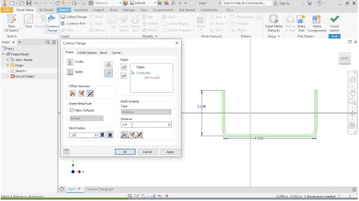
The Contour Flange Feature in Autodesk Inventor
Other Important Sheet Metal Features You’ll Come Across
- Tabs: a feature that can be created in Inventor sheet metal by using the face tool’s join option
- Hem: a tool used to fold over an edge of a sheet metal part
- Corner Round: a command used to add rounds to sheet metal faces
- Corner Chamfer: a tool that offers various options with different parameters for removing sharp corners from flat sheet metal parts
- Cuts across bends: a feature to create a cut along flattened geometry, replicating how sheet metal parts are manufactured
Learning these common sheet metal features will allow you to fold and unfold parts, create new features, and create 2D drawings for use in manufacturing and fabrication. Take our online Inventor Sheet Metal training course to further explore sheet metal and explore hundreds of other SolidProfessor tutorials and courses.

An engineer in front of a fabrication machine.
Image Credit: Stock.Adobe.com/Pixel_B