All About Plastic Extrusion


A guide to understanding this plastic manufacturing process and all that it can do


There are many plastic processing methods available, but there’s one in particular that has managed to solve the inconsistencies and problems that come with making longer pieces—plastic extrusion. Since 1935, manufacturers have leaned on this technique to make products that are longer or require more material, like tubes and trim. If you’re interested in plastic extrusion for your own products and business, we’ve written up a more detailed explainer for this process.
What is Plastic Extrusion?
In the simplest definition, plastic extrusion is a process that melts and molds plastic into different shapes and is done on a pretty large scale. When you put it up against other types of plastic manufacturing, you’ll find this method is better for creating objects that are longer or wider as the machine can properly funnel out a continuous tube, pipe, or sheet of plastic. The applications for plastic extrusion are almost as varied as the types of plastic you can choose between (more on the types available below). Just a few of these include:
- Tubes, fuel lines, and pipes for plumbing and farming
- Doors, window frames, trim, weatherstripping, and decorative moldings
- Insulation and coatings for wires and cables
- Packaging materials and containers for objects, food, and beverages
- Plastic films and sheets
- Straws and utensils
Plastic extrusion requires specialty equipment that’s capable of pumping out long lengths of plastic. Most of these machines have a container to hold the melted plastic, a barrel to funnel it forward, and a die and cutter to shape the product. You can get an idea of how this looks in the image below.
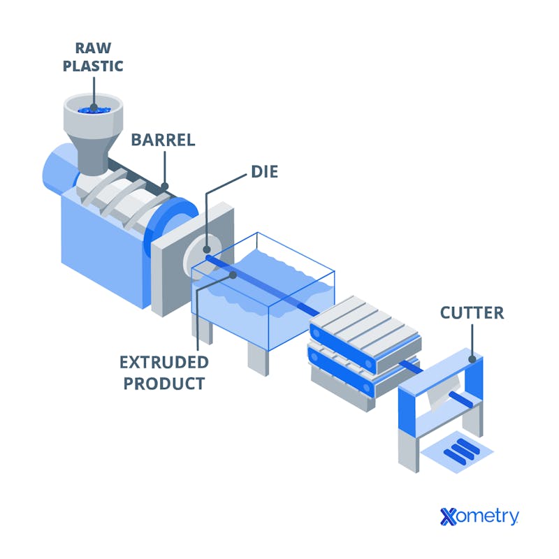
Illustration of the plastic extrusion process melting and extrusion stage.
The magic happens when all of these components function correctly. Here’s a step-by-step breakdown of how it all works:
- First, raw plastic pellets or granules will be poured and stored in a hopper—the material will depend on what you’re making and could be anything from polycarbonate to ABS.
- Then the plastic will move into a heated barrel (usually sitting around 200 to 275 ℃) and start melting down into a molten state for easy molding. Inside of this barrel is a screw that’ll rotate at a consistent speed. This keeps the pellets moving and melting at the same rate.
- After it’s melted, the extrusion begins and the molten plastic will move past the screw and through a screen to get rid of contaminants. Then it’ll pass through a die cut into the specific shape needed, which will give the plastic its shape.
- Once it reaches this point, the plastic will either go through a water- or air-based cooling system. This cools the temperature and allows the plastic to fully harden.
- After cooling, the pipes, sheets, tubes, or other shapes will get hauled across rollers and then cut down to the necessary length. If the piece needs further processing, like finishing or adding other components, this is when it would get done.
- The plastic objects will then get checked again to ensure they’re accurate and up to par, quality-wise.
All in all, plastic extrusion is pretty quick, but the timeline can slow if you’re making complex parts or if your objects need to go through intense post-processing. Here’s a picture of a piece of trim that was made through plastic extrusion:


Cost-wise, it all comes down to the type of plastic you choose. For the product materials, you can expect an average of $1,000, whereas the machinery can be a sum of anything between $7,000 to $90,000 depending on the size of your operation and the complexity of the parts you’re making.
Material Types and Selection
Picking out the right plastic all depends on what you need the final product to do. It might be sitting outside and exposed to UV rays from the sun or extremely cold and hot temperatures, in which cases environmental resistance is important. It could also be a container or method of transporting acids and solutions, so resistance to harsh chemicals is a necessity. Equally, it may just need to look nice and not have too many fancy mechanical properties. To give you some examples of common plastics used for extrusion, we’ve listed out eight below and what they’re good for.
Polyethylene (PE): This plastic is used to make things pipes, packaging, and containers, because it’s chemical-resistant, flexible, and durable, with the added perk of being cost-effective, too. It comes in different types, including low-density (LDPE) and high-density (HDPE).
Polypropylene (PP): Made with fossil fuels, PP has a high melting point, can make strong and impact-resistant products in many colors, like textiles, vehicle parts, and packaging.
Polyvinyl chloride (PVC): If cost and durability are both important, PVC is a good option. There are two types that manufacturers usually pick between: rigid and flexible. The former is best for products that you know will get exposure to radiation and a certain level of impact, whereas flexible is good for tensile strength and weatherproofing. These include windows, doors, pipes, and refrigerators.
Polystyrene: Polystyrene’s rigid nature makes it ideal for extruded products that get used for packaging and insulation.
Acrylonitrile butadiene styrene (ABS): ABS is a common material for 3D printing, but it plays a big part in plastic extrusion, too. It’s often sought out because its finish is shiny and aesthetically pleasing, which can’t be said for all plastics.
Polyamide (PA or nylon): Nylon is prized for its fantastic mechanical properties, like heat stability and chemical resistance. Depending on the type you use, it makes for great automotive parts and textiles.
Polycarbonate (PC): Using polycarbonate for plastic extrusion is another great in-between for manufacturers since it’s rigid, heat stable, and resistant to abrasion—although it tends to be more expensive. It’s a go-to for items like car components and enclosures for electronics.
Polyethylene terephthalate (PET): PET is another common plastic, used for food and beverage containers, engineering applications, and as a fiber for making textiles for clothes and home goods.
Comparing Plastics
We’ve put together a simple table that shows what kind of cost, chemical and mechanical properties, and rigidity you can expect from different types of plastics that are used for extrusion:
| Material | Heat Stability | Chemical Resistance | UV Resistance | Rigidity | Cost |
|---|---|---|---|---|---|
Material ABS | Heat Stability Fair | Chemical Resistance Poor | UV Resistance Poor | Rigidity High | Cost Medium |
Material PVC | Heat Stability Poor | Chemical Resistance Poor | UV Resistance Poor | Rigidity Varies | Cost Medium |
Material Low Density Polyethylene (LDPE) | Heat Stability Poor | Chemical Resistance Good | UV Resistance Poor | Rigidity Poor | Cost Low |
Material High Density Polyethylene (HDPE) | Heat Stability Fair | Chemical Resistance Good | UV Resistance Fair | Rigidity High | Cost Low |
Material PETG | Heat Stability Poor | Chemical Resistance Excellent | UV Resistance Good | Rigidity Medium | Cost Medium |
Material UHMW PE | Heat Stability Poor | Chemical Resistance Good | UV Resistance Poor | Rigidity Medium | Cost Low |
Material Polypropylene (PP) | Heat Stability Excellent | Chemical Resistance Excellent | UV Resistance Poor | Rigidity High | Cost Low |
Material Nylon | Heat Stability Excellent | Chemical Resistance Excellent | UV Resistance Fair | Rigidity High | Cost High |
Material Polycarbonate (PC) | Heat Stability Excellent | Chemical Resistance Fair | UV Resistance Excellent | Rigidity High | Cost High |
Pros and Cons
When you’re planning to manufacture products using plastic extrusion, these are the advantages you’ll find in doing so:
- This is a cheaper option than other types of plastic manufacturing.
- The continuous nature of plastic extruded products means they’re easier to create and there’s less likely to be severe inventory shortages.
- After being extruded, it’s possible to tweak the products before they permanently cool down and harden.
- You can create a wide range of shapes and circumferences with a plastic extrusion machine with the right die and extruder.
- You won’t feel limited by types of material, especially with how many plastics exist.
Here are a few drawbacks to keep in mind:
- Swelling is a possibility, which happens before the products cool down.
- It isn’t the best or most efficient manufacturing method for all types of plastics, and you’ll find that not all plastic products can be made via extrusion.
- The cost of machinery and dies is extremely expensive compared to other techniques.
- It’s really difficult to use recycled plastics with extrusion machines since they’re built to filter out impurities.
Manufacturers may notice that extreme accuracy with plastic extrusion—especially when it comes to intricate parts—isn’t always possible. This could be due to cooling rates, how much the die swells, or a number of other reasons. In these cases, it might be better to lean on die casting, 3D printing, or plastic injection molding for getting the exact design you need. Still, today’s modern machines have even better capabilities than the ones that came before them and there’s much more control over dimensions and how the output looks.
Tips for Designing Products for Plastic Extrusion
Avoid annoying mishaps and stay from serious design flaws with these design tips from our team at Xometry:
Keep Wall Thickness Consistent
Inconsistent wall thickness could lead to uneven cooling, so keeping these consistent and quite sizable will avoid warping and twisting. A good rule of thumb is not having walls thinner than 0.025 inches.
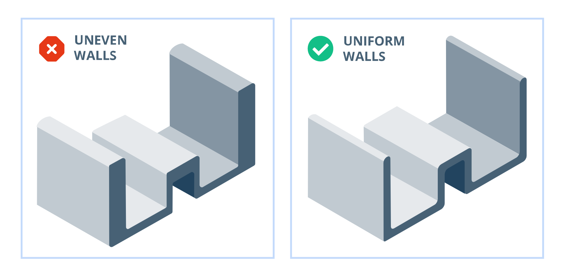
Extrusion design with uneven wall thickness vs. uniform wall thickness.
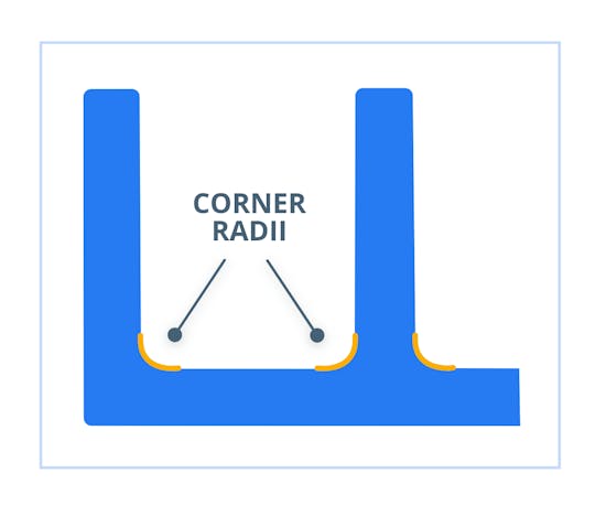
Diagram of an extrusion cross-section depicting proper use of corner radii
Avoid Designing Hollows
Hollows are called lumen in plastic extruding terms, and while it’s possible to create these features, they can cause problems because of the more simplistic design of the extrusion machine. There aren’t ways of affecting air pressure or creating a vacuum, so these areas can collapse or deform. If you have to include lumen, don’t design cavities within cavities and keep protrusions to a minimum.
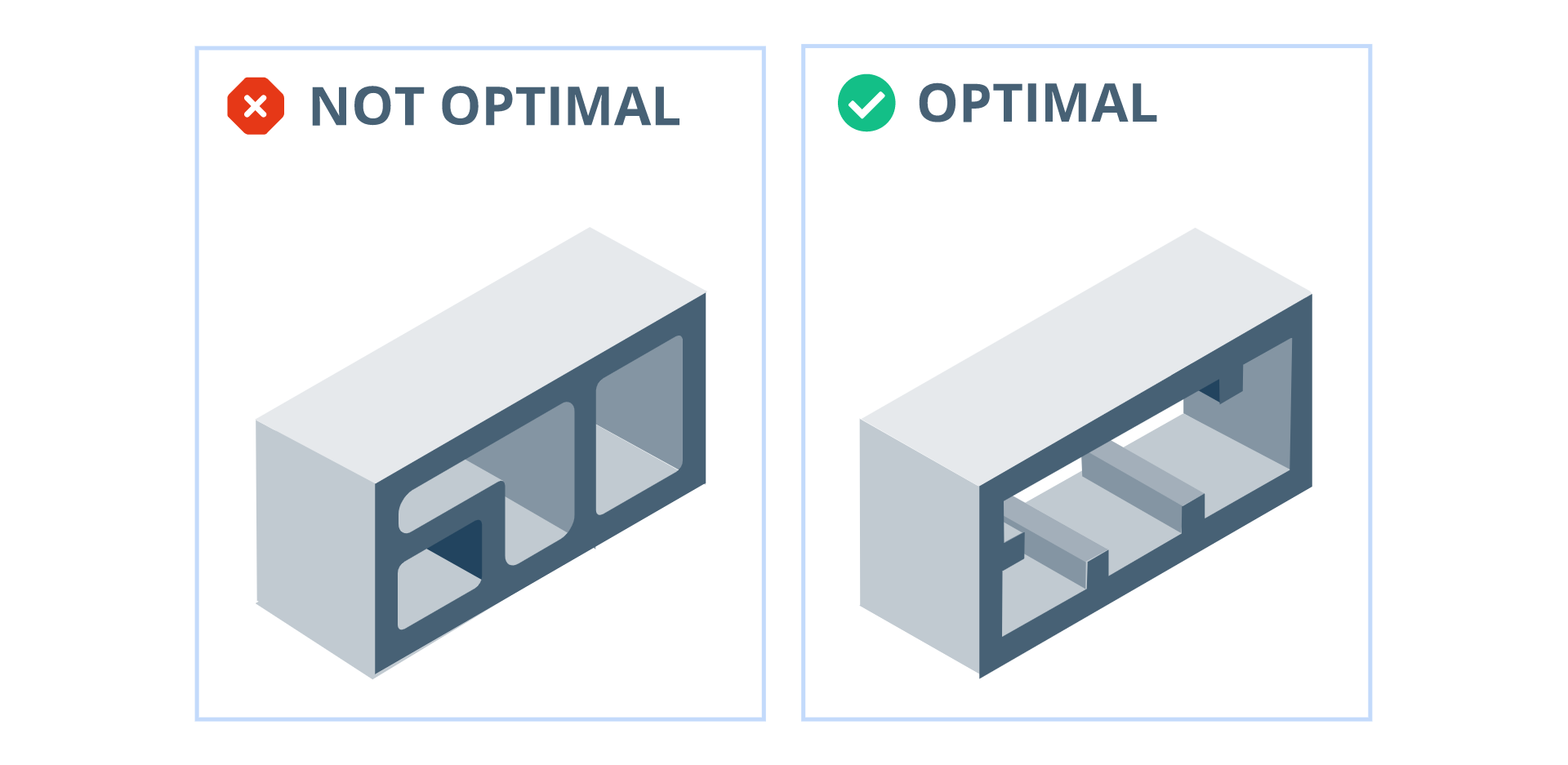
An extrusion design with excessive hollows compared to an optimal design.
Avoid Tight Tolerances
If you have extremely precise and specific measurements, plastic extrusion probably isn’t the manufacturing method for you. There’s a chance of swelling, deformation, and changes in the final product. Aim for standard tolerances and if you have tight tolerances for precise parts, make sure you have the tools and machinery to make this happen or use a different technique.
How Xometry Can Help
Plastic extrusion isn’t the only plastic-focused process Xometry offers. We have a long list of other services that can handle everything from PET to HIPS, including custom plastic injection molding, plastic 3D printing, plastic laser cutting, and custom plastic fabrication.

Disclaimer
The content appearing on this webpage is for informational purposes only. Xometry makes no representation or warranty of any kind, be it expressed or implied, as to the accuracy, completeness, or validity of the information. Any performance parameters, geometric tolerances, specific design features, quality and types of materials, or processes should not be inferred to represent what will be delivered by third-party suppliers or manufacturers through Xometry’s network. Buyers seeking quotes for parts are responsible for defining the specific requirements for those parts. Please refer to our terms and conditions for more information.