How to Choose Core and Cavity Placement in Injection Molding


The best practices to follow in mold design


The mold is the most important part of any injection molding process, as the success of every product that goes through the machine depends on it. Making molds is time-consuming and expensive because you don’t have just one part to think about; the inside (the core) and the outside (the cavity) of the mold both need to be designed just right for the part to come out perfectly. Deciding exactly where to put cores and cavities in the mold design is tricky, but in this article we’ll give you some top tips on finding the best placement for them on your mold.
Basics of Injection Molding
Before discussing where to place cores and cavities, it is necessary to explain how injection molding works and how it impacts design considerations in the first place. The basic injection molding cycle steps are as follows:
- Plastification: This is where the plastic pellets are melted with high heat and move through a reciprocating screw in the machine’s hopper. The screw will then push the material through the heater bands and melt it.
- Injection: The screw continues to push the melted plastic further into the mold, which is made up of the two clamped halves (core and cavity).
- Packing/cooling: The mold is kept at a set temperature under a holding pressure until it has cooled down and solidified.
- Demold/ejection: This is where the two halves of the mold open and ejector pins are used to push the final product out from one side.
What Are Cores and Cavities?
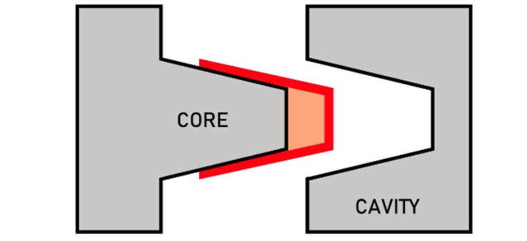
As briefly covered in the intro, the core of a mold is the inside part that you can’t see, and the cavity is the exterior surface that will be visible and treated or polished as necessary. When they are put together in injection molding, melted plastic will fill the thin space between them and harden into the final part. But why is the placement of these mold parts so important? Well, an adequately-designed mold will ensure the plastic flows and cools well, and that the part can be easily removed when it’s hard. There are four steps in the process, which are shown in the diagram below.


What Affects Core and Cavity Placement?
It is vital to determine the best arrangement of mold components, otherwise the injection molded part will fail. The above image intentionally removes many parts of a mold to highlight the core and cavity but note that there are several components and concepts that will affect the core/cavity placement (and the success of the project). Below is a short list of what affects core and cavity placement:
Part shape: the above image shows a simple, cylindrical shape, but many injection molded parts are highly complex. The part shape will not only determine where to place the core and cavity in the mold, but also where ejector pins, cooling channels, and other necessary components go (which in turn affect core and cavity placement, etc.). Also uniform wall thickness is a priority in part shape, as variable wall thicknesses will cause issues in both cooling and ejection.
Ejector System: When the mold is opened after the cooling stage, the injection molded part must ALWAYS be stuck to the side of the mold with the ejector pins. The ejector system and its specific shapes will affect where the core and cavity are placed so that consistent, repeatable ejection is achieved.
Material: The shrink rate, flow characteristics, and injection speed of a material will partly dictate how the core and cavity are arranged. If a material has a low shrink rate, then it will be more difficult to get the part to stick to the ejector pin side, therefore calling for design considerations. Luckily most plastics do shrink considerably, but it is important to understand how the material could potentially affect where the core and cavity should go.
Gates, Runners, and Sprues: The sprue is the main channel from the injection molding nozzle that feeds plastic into the mold cavity. It is typically perpendicular to the mold cavity’s axis but can sometimes be directly piped into the cavity (in that instance, the sprue is known as a direct sprue gate). Runners are the channels that feed multiple mold cavities with molten plastic from the sprue. Most injection molds use runners as iit is more economical to mold multiple parts in one cycle (especially small parts like model kit parts, for example). Gates are the entry points from the runner into the core and cavity and are typically much narrower than the runner.
Each of these components affect core and cavity placement and must be smartly designed. The sprue and runner locations must be placed in such a way that allows for sufficient filling of all features of a part. Proper gate location affects core and cavity placement, as they influence how the core and cavity fills and how the part will look aesthetically, as it is the point the part is cut off from the runner system (assuming a cold runner design).
Core and Cavity Placement Considerations
Our team of experts has put together a few tips and tricks on the best way to design and arrange core and cavity placement in an injection molded part.
Core and Cavity Design
To reduce the chance of defects and make the ejection process a lot smoother and cleaner, here are a few pointers that limit where, and in what orientation, you can add the features:
- Include rounded corners or edges
- Add ribs for supports
- Add bosses for threaded inserts
- Try to avoid vertical walls (perpendicular to the mold’s parting line)
- Use uniform wall thickness as much as you can
- Create hollow cavities in thick sections
The core and cavity shown in two mold halves.
Core and Cavity/Christian Cavallo Consulting LLC
Complex parts will need you to set aside some extra designing time. Going for rounded corners and hollow sections will generally make molding easier. To avoid the final part getting trapped in the mold, you’ll have to ensure that the part is stuck to just one side of it—the one with the ejector pins.
Draft angles
One especially important aspect of core and cavity design is the draft angle, which is the angle of the walls to the mold’s vertical axis. Its purpose is to take shrinkage into account and allow for easy ejection, as well as prevent any damage during removal. Here’s what it looks like:


When plastic is perfectly vertical in a mold design—especially inside a cavity or around a core—it will experience friction and suction as you try to remove it from the mold. But you can reduce the friction and release the vacuum by providing space and designing proper draft angles. Along with the core and cavity placement, draft angles can also be used to keep the part on the right side of the mold.
All these points contribute in one way or another to the placement of the core and cavity. Not only does everything need to fit together well to keep the process smooth and safe, but you also need to think about how the final part needs to look aesthetically, too. In the image below, we illustrate the plastic mold feed system that’s usually used with this type of molding:

Machining Considerations
You’ll want to keep in mind your material characteristics like flow rate, heating and cooling temperatures, and shrinkage rate. The more fabricating processes you put your mold through, the more chances there are of it coming out with a less-than-adequate surface finish.
Filling, Thermals, and Shrinkage
Some of our customers find it helpful to first decide on the material before designing their mold. Most plastics shrink well, but they react differently when put through various processes. For instance, materials with a low shrink rate are harder to stick to the side with the ejector pins.
Using CAD software, like Autodesk Fusion and Moldflow, Solidworks Plastics, ZW3D, and Moldex3D, can help in more ways than one. These can help you predict how a given design will function by simulating shrinkage, temperatures across a cycle, and how evenly core and cavities are filled through a runner system. These software options will help you decide where to place the core and cavity, and even offer up suggestions, help you keep milling, cutting, tapping, or any other process to a minimum, ultimately saving you both time and money.
Sprues, runners, gates
A sprue is the main channel that feeds the plastic from the nozzle into the mold cavity. Most of the time, it’s placed at a right angle to the axis of the cavity, but sometimes it can be directly piped into it (known as a direct sprue gate). Runners are the channels that feed the melted plastic from the sprue into the mold cavities. Most molds actually use runners because it works out to be more economical to make several parts in one cycle. Gates are the entry points from the runner into the core and cavity. They’re typically much narrower than the runner.
How Xometry Can Help
For more advice and personalized tips on core and cavity placement in your molds, feel free to reach out to one of our reps. We can also help you out with the actual injection molding process, too. You can also get a quick and easy free quote for any one of our manufacturing services, including CNC machining, 3D printing, and laser cutting.
Disclaimer:
The content appearing on this webpage is for informational purposes only. Xometry makes no representation or warranty of any kind, be it expressed or implied, as to the accuracy, completeness, or validity of the information. Any performance parameters, geometric tolerances, specific design features, quality and types of materials, or processes should not be inferred to represent what will be delivered by third-party suppliers or manufacturers through Xometry’s network. Buyers seeking quotes for parts are responsible for defining the specific requirements for those parts. Please refer to our terms and conditions for more information.