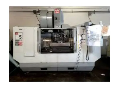
40 Parts of a CNC Machine and Block Diagram of CNC Components


40 Parts of a Computer Numerical Control (CNC) Machine and Block Diagram of CNC Components provide a detailed overview of the elements that make a CNC machine function with precision and efficiency. The 40 Parts of a CNC machine and Block Diagram of CNC components illustrate how each component, from motion control and workholding to structural rigidity, feedback systems, and operator interface, contributes to machine performance. CNC machines integrate mechanical and electrical subsystems, including input devices, control units, spindles, motors, guideways, and auxiliary systems (coolant and lubrication). Proper maintenance, alignment, and replacement schedules ensure accuracy, reduce downtime, and lengthen the machine’s lifespan. Components are categorized into control systems, motion systems, structural systems, feedback, workholding, and auxiliary systems.
40 Parts of a CNC Machine and Block Diagram of CNC Components are shown in the table below.
1. Input Device
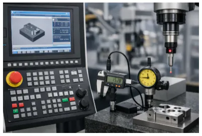
An input device is a hardware component that captures user commands, physical signals, or environmental data and converts it into digital information for processing by computers or manufacturing systems. Input devices allow precise control, accurate data entry, and workflow automation, improving design accuracy, reducing production errors, and supporting real-time monitoring in digital manufacturing. The common industrial input devices include keyboards, touchscreens, scanners, sensors, probes, cameras, HMIs, and control panels. Input devices allow machines and software to execute commands, verify specifications, monitor tolerances, and maintain consistent production outcomes by translating physical actions or measurements into electrical signals.
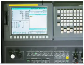
2. Machine Control Unit (MCU)
A Machine Control Unit (MCU) is the central control component of a manufacturing machine that interprets digital instructions and converts them into precise mechanical movements. CNC and automated systems control motion, tool positioning, spindle speed, and coordination between machine components. The MCU allows high accuracy, repeatability, and consistent production by executing programmed instructions with minimal human error, supporting efficient fabrication of complex parts. The common MCU types are CNC controllers, PLC-based control units, embedded motion controllers, and integrated controllers for multi-axis machines. The machine control unit (MCU) ensures accurate motion control, proper tool paths, and adherence to programmed specifications, by translating G-code or machine instructions into electrical signals and monitoring sensor feedback.
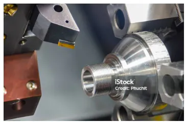
3. Machine Tools
Machine tools are mechanical systems used to shape, cut, form, or finish raw materials into precise components by controlling tool movement. Machine tools function as the mechanical assembly that executes physical material removal, following the motion and logic provided by the driving and control systems to maintain design specifications. The tools are fundamental to manufacturing processes (CNC machining, metalworking, and custom part production). Machine tools support consistent, repeatable, high-precision manufacturing through reduced manual intervention, improved cycle efficiency, and accurate production of complex geometries with tight tolerances.
Common types include turning machines (lathes), milling machines, drilling machines, grinding machines, electrical discharge machines (EDM), and non-contact cutting systems (laser machines, waterjet machines). Machine tools convert manual or digital commands (CNC G-code) into controlled tool motion through motors, actuators, and servo systems. Sensor feedback loops monitor position, speed, and load conditions to maintain dimensional accuracy and surface quality within specified tolerances.
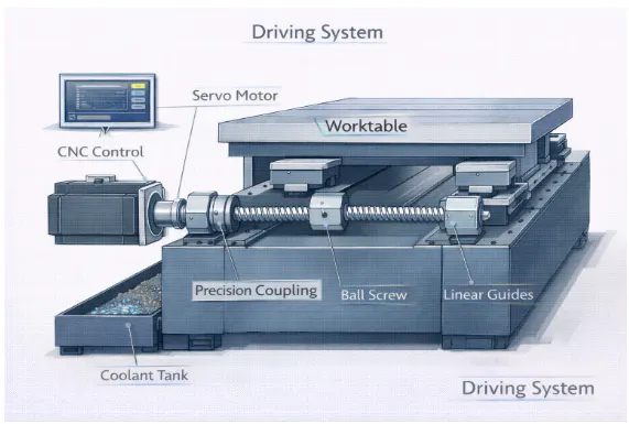
4. Driving System
A driving system in manufacturing refers to the assembly of components that convert energy from motors or engines into controlled motion for machine parts, allowing processes (rotation, linear movement, or tool actuation). Driving systems are critical for CNC machines, robots, and automated equipment, providing precise, reliable, and repeatable motion that improves efficiency, reduces errors, and supports consistent production of complex geometries. Driving systems utilize power sources, such as electric motors (stepper, servo, or brushless) or hydraulic or pneumatic actuators, coupled with mechanical transmissions (belts, chains, or gears) to achieve precision and power. The driving systems function by receiving control signals from a machine controller and moving components with defined speed, direction, and force, while sensors provide feedback on position, speed, and load to ensure accuracy and maintain high-quality manufacturing.
5. Feedback System
A feedback system is a mechanism that monitors process outputs and uses output data to adjust system inputs, maintaining controlled performance relative to defined setpoints. A feedback system requires a return signal path from output to input, which enables comparison, correction, and regulation.
Control systems are categorized as open-loop or closed-loop. Open-loop control systems operate without monitoring output and therefore do not contain a feedback signal path. Closed-loop control systems utilize a feedback signal to continuously compare actual output with the desired setpoint and adjust inputs accordingly.
Feedback systems are further classified as positive or negative. Positive feedback reinforces deviations and amplifies system response. Negative feedback counteracts deviations and stabilizes system behavior by reducing error.
Feedback systems function through sensors that measure performance variables, controllers that compare measured values to reference setpoints, and actuators that implement corrective input changes. Continuous measurement and correction maintain stability, accuracy, and operational reliability within defined tolerance limits.

6. Display Unit
A display unit is an interface device that visually presents information from a machine or system, allowing operators to monitor and interact with processes. Display unit improves operational efficiency by providing real-time data visualization, allowing quick and accurate decision-making while reducing errors. Display units come in various types, like Liquid Crystal Display (LCD), Light Emitting Diode (LED), touchscreen, and graphical displays. Receiving data from sensors or controllers, processing the information, and presenting it in an easy-to-understand visual format, with touchscreen models allowing direct input to control machine operations, are their functions.
7. Bed
The bed in CNC machinery refers to the primary structural base that supports core components such as the worktable, spindle assembly, guideways, and drive systems. The bed provides rigidity and geometric stability during machining operations, maintaining alignment under cutting forces and dynamic loads. Structural stiffness of the bed limits deflection and preserves dimensional accuracy during high-speed operations.
Cast iron beds are known for high internal damping capacity, which effectively suppresses vibrations generated during cutting. Graphite flake structures within cast iron dissipate vibrational energy through internal friction mechanisms. Granite and mineral casting beds offer superior thermal stability due to low thermal expansion characteristics and provide even higher vibration-damping performance for precision applications. Material selection directly influences thermal deformation control, surface finish consistency, and long-term machine accuracy.
The bed supports the full weight of the workpiece and moving assemblies while maintaining the levelness of linear guides and ball screw systems. Stable bed construction remains critical for achieving repeatable positioning accuracy and consistent machining performance
8. Headstock
The headstock is a component of a lathe or machine tool that holds and rotates the main spindle, driving the workpiece during machining operations. Headstock supports precision cutting, consistent performance, and high-quality finished parts by ensuring accurate and controlled rotation. Headstocks come in various types (spindle, geared, and belt-driven), and each is suited to different power transmission and speed requirements. The headstock houses the spindle assembly, bearings, and often a transmission system (gears or belts) that transmits power from the motor to the spindle for the workpiece or tool. The design ensures rigidity and alignment, minimizing vibration and deflection, which is necessary for maintaining machining accuracy and prolonging the life of the workpiece and the machine tool.
9. Tailstock
The tailstock is a machine component positioned opposite the headstock that provides support to the free end of a workpiece during the machining of long or slender parts. Tailstock reduces deflection, vibration, and bending by stabilizing the workpiece, which improves machining accuracy and surface finish. Tailstocks are manual, hydraulic, or pneumatic, depending on the type of operation and level of automation required. They are designed to slide along the machine bed and be locked securely in position. The tailstock holds centers, drills, reamers, or other tools to support or perform operations on the workpiece; offset tailstocks specifically can be used to facilitate the turning of long tapers.
10. Tailstock Quill
The tailstock quill is the extendable spindle of a tailstock that holds tools (drills, reamers, or centers), providing crucial support for machining operations. The tailstock quill allows precise axial movement of tools, allowing accurate drilling, reaming, and alignment of the workpiece while maintaining stability and reducing errors. Tailstock quills are available in manual, hydraulic, or screw-driven types, offering varying levels of control, force, and automation for different machining tasks. The quill slides smoothly within the tailstock housing and is controlled through a handwheel, hydraulic mechanism, or screw drive, allowing precise positioning, controlled feed, and consistent operation. Smooth sliding movement and controlled operation of the tailstock quill ensure high accuracy, repeatability, and versatility in turning, tapering, and drilling operations, making the tailstock quill an important component for precision machining and efficient workflow.
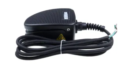
11. Footswitch or Pedal
A footswitch, or pedal, is an input device operated by the foot to control machine operations (starting, stopping, or adjusting the speed of a machine). A footswitch allows hands-free operation, enhancing workflow efficiency, precision, and safety by allowing the operator to focus on other tasks while maintaining control over critical machine functions. Footswitches come in different types, including momentary, which activates only while pressed; latching, which toggles functions on or off; and multi-function pedals, which control several machine operations simultaneously. The footswitch sends electrical signals to the machine controller, triggering specific actions (motor start/stop, speed adjustment, or tool engagement). The footswitch design improves operator ergonomics, reduces fatigue during repetitive tasks, and supports integration with CNC machines, automated equipment, and production systems, making it a versatile and essential component in modern manufacturing and industrial operations.
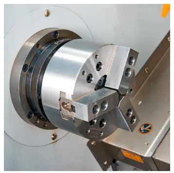
12. Chuck
A chuck is a specialized workholding device used to secure a workpiece or a tool during machining operations. It is typically mounted on the machine spindle and provides high clamping force to ensure stability and accuracy during rotation. Chucks are available in various types, including three-jaw self-centering chucks for cylindrical parts, four-jaw independent chucks for irregular shapes, and collet chucks for high-precision, small-diameter work. The chuck operates by moving its jaws or collet radially to grip the object, and it can be actuated manually, pneumatically, or hydraulically. Proper selection and maintenance of the chuck are essential for maintaining concentricity, preventing workpiece slippage, and ensuring operator safety in high-speed CNC turning and milling processes.
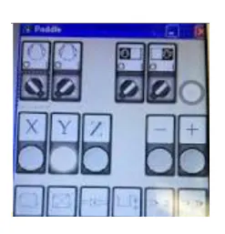
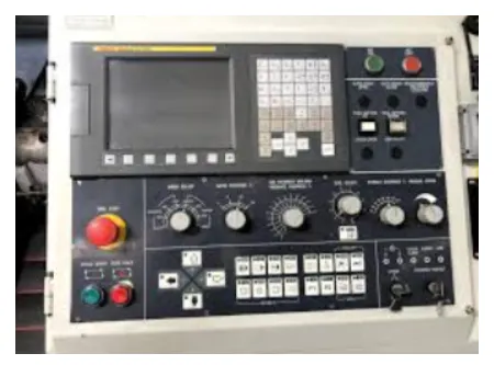
13. Control Panel
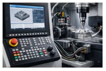
A control panel is the interface where operators manage, monitor, and control machine tool operations. Control panel centralizes machine control, improving precision and efficiency while allowing operators to adjust parameters quickly. Control panels come in various types, including push-button panels, touchscreen CNC panels, and digital display panels. The control panel receives inputs from the operator, communicates with the machine controller, and displays machine status or error messages. Control panel allows selection of operational modes, speed settings, and commands, providing a user-friendly interface that improves workflow, reduces errors, and ensures reliable machine performance.
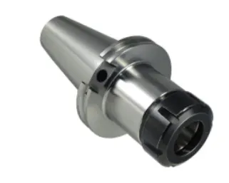
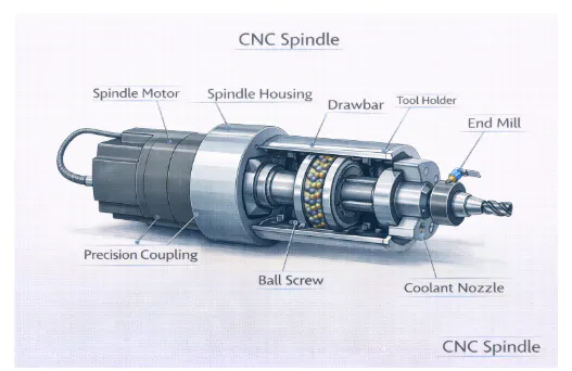
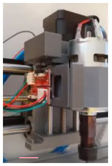
14. CNC Spindle
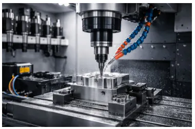
The CNC spindle is the rotating component of a machine tool that holds and drives cutting tools during machining operations. The CNC spindle allows high-speed rotation and precise control, ensuring accurate material removal, consistent cutting, and smooth surface finishes. Spindles can be belt-driven, direct-drive, or gear-driven, depending on the required speed, torque, and application. The CNC spindle receives power from the motor and transmits rotational motion to the cutting tool, maintaining consistent speed and torque throughout machining. Its design ensures stability, minimizes vibration, and allows for precise and efficient cutting, making it a critical component in achieving high-quality machining results.
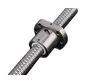
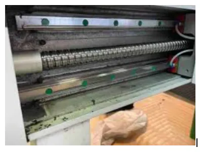
15. Ball Screws
Ball screws are mechanical devices that convert rotational motion into linear motion with high efficiency and precision. Ball screws reduce friction, improve positioning accuracy, and enable smooth, reliable linear movement in CNC machines and other precision equipment. Available in rolled and ground manufacturing types, with various preloading configurations to adjust accuracy, load capacity, and stiffness. Ball screws operate through recirculating balls between the screw and nut, which transmit force efficiently while minimizing friction. This efficient force transmission allows precise linear motion, enhances machine responsiveness, supports high-speed operation, and ensures consistent accuracy for precise machining and automated applications.
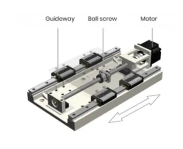
16. Linear Guideways
Linear guideways provide precise linear motion for machine components while supporting heavy loads and minimizing friction. Linear guideways improve stability, accuracy, and repeatability in machine operations, making them important for CNC machines, automation systems, and precision equipment. Guideways come in various types, including profile rail guides, ball-type guides, and roller-type guides, each designed to accommodate different load capacities and motion requirements. Linear Guideways function through rolling elements between the rails and carriages, allowing smooth, straight-line motion with minimal resistance, reducing wear, and ensuring consistent performance over time.
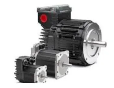
17. Servo Motors
Servo motors are precision motors that provide controlled rotational or linear motion for CNC machines and automated systems. Servo motors allow accurate positioning, precise speed control, and smooth operation, supporting high-precision machining and automation tasks. Servo motors are available in various types, primarily categorized as AC or DC, with brushless designs being the standard for high-performance CNC applications. They receive control signals from machine controllers and adjust position, speed, and torque precisely, using feedback from encoders to ensure accurate motion, repeatability, and reliable operation in complex manufacturing processes.
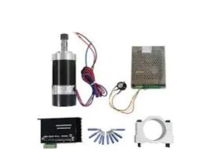
18. Stepper Motors
Servo motors are available in various types, primarily categorized as AC or DC, with brushless designs being the standard for high-performance CNC applications. Stepper Motors offer reliable, repeatable positioning, making them ideal for CNC machines, robotic systems, and other automated applications. Stepper motors come in various types, including permanent magnet, variable reluctance, and hybrid steppers, each designed for different torque, speed, and precision requirements. Stepper motors rotate incrementally in response to pulse signals from controllers, enabling accurate positioning, consistent motion, and precise control over complex mechanical movements.
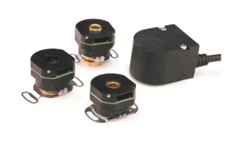
19. Encoders
Encoders are devices that convert motion or position into electrical signals, providing feedback to a control system. Encoders allow precise motion control, improve accuracy, and support closed-loop operation in CNC machines, robotics, and automated systems. Encoders come in various form factors, such as rotary and linear, and utilize different sensing technologies, including optical and magnetic, to meet specific feedback requirements. Encoders detect movement or changes in position and transmit signals to controllers, allowing real-time monitoring, correction, and adjustment of machine motion, ensuring high precision, repeatability, and reliable performance in complex manufacturing processes.
20. Limit Switches
Limit switches are devices that detect the presence, absence, or position of a machine component. Limit switches improve safety, prevent overtravel, and ensure precise stopping points during machine operation. Limit switches come in various types, including mechanical, magnetic, and optical, each suited to different sensing requirements and environments. Limit switches activate when a component reaches a predefined position, sending signals to controllers to stop, start, or reverse motion. Limit switches protect machines, maintain operational accuracy, and help prevent damage to equipment and workpieces, by providing reliable position feedback.

21. Home Switches
Home switches are devices that establish a reference or zero position for machine axes during startup. Home switches improve repeatability, ensure consistent positioning, and provide a reliable baseline for accurate machining operations. Home switches are available in mechanical, optical, and magnetic types, each suited to different precision and environmental requirements. Home sensors signal the machine controller when an axis reaches its home position, allowing the system to reset positions accurately and maintain precise alignment during operation, ensuring reliable performance and consistent results in CNC machines and automated systems.
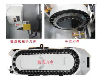
22. Tool Magazine
A tool magazine is a storage system on a CNC machine that holds multiple cutting tools for automated tool changes. Tool Magazine reduces downtime, increases productivity, and enables complex machining operations without manual intervention. Tool magazines come in various types, including carousel, chain, and linear configurations, each designed for different capacities and space requirements. The tool magazine stores and presents the required tool for the automatic tool changer, ensuring continuous operation, improving workflow efficiency, and supporting high-precision, multi-step manufacturing processes.
23. Automatic Tool Changer (ATC)
The automatic tool changer (ATC) is a mechanism that swaps cutting tools automatically during CNC operations. An automatic tool changer increases productivity, guarantees consistent machining quality, and reduces the need for manual intervention. ATCs are available in different types, including carousel-type (or drum), chain-type, and rack-type, each designed for different tool capacities and machine configurations. The ATC withdraws the required tool from the tool magazine and places it into the spindle while returning the previous tool to storage, enabling seamless tool changes during machining cycles. Automatic Tool Changer (ATC) automation optimizes workflow efficiency, minimizes downtime, and supports complex, multi-step manufacturing operations with high precision
24. Coolant System
The coolant system supplies liquid or mist to machine tools and workpieces to reduce heat generated during cutting. The coolant system prevents thermal damage, extends tool life, and improves surface finish, ensuring high-quality machining. Coolant systems come in different types, including flood, mist, and through-spindle configurations, each designed for specific cooling and chip-removal requirements. The coolant circulates through positioned nozzles onto the cutting area, dissipating heat and flushing away chips from the machining zone. The coolant system process maintains dimensional accuracy, improves tool performance, and supports efficient, continuous operation in CNC machines and other precision equipment.
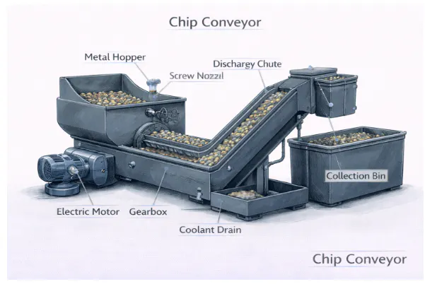
25. Chip Conveyor
A chip conveyor is a device that removes metal chips, swarf, or debris from the machining area. Chip conveyors help maintain a clean workspace, prevent machine jams, and improve operator safety. Chip conveyors are available in various types, including belt-type, chain-type, and auger-type, each suited for different chip sizes, volumes, and machine configurations. The conveyor collects chips from the machine bed and transports them to a designated disposal area, keeping the machining zone clear and ensuring continuous, efficient operation. Chip conveyors protect machine components, reduce downtime, and support high-quality, uninterrupted manufacturing processes by managing debris effectively.
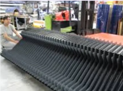
26. Way Covers
Way covers are protective shields that cover machine guideways to prevent dust, chips, and coolant from contaminating precision surfaces. Way covers prolong the life of guideways, maintain machining accuracy, and reduce maintenance requirements. Way covers come in various types, including bellows (accordion), telescopic steel, and roll-up covers, each designed for specific machine geometries and movement ranges. Functionally, they slide or fold as the machine moves, effectively blocking debris from reaching the guideways while allowing smooth, unobstructed motion. Way covers ensure long-term precision, reliability, and efficient operation in CNC machines and other precision equipment by protecting critical surfaces.
27. Lubrication System
The lubrication system ensures smooth operation, prevents overheating, minimizes component wear, and extends the life of machine elements. Lubrication systems can be manual, automatic, or centralized, depending on the level of automation and machine complexity. The lubricant is distributed through pipes, nozzles, or fittings to critical moving parts, maintaining smooth motion, reducing friction, and protecting against corrosion. Ensuring consistent lubrication, lubrication systems improve machine reliability, performance, and efficiency in CNC machines and other industrial equipment.
28. Hydraulic System
A hydraulic system generates, controls, and transmits power using pressurized fluid. The hydraulic system delivers strong force, accurate control, and smooth movement, making it effective for operating heavy machine parts. Hydraulic systems can be divided into open-center, closed-center, and electro-hydraulic types, each designed to meet specific performance and control needs. The system works by pressurizing hydraulic fluid and directing it through valves to actuators, which then move components with precise force and motion. Hydraulic systems convert fluid energy into mechanical action, providing dependable, high-performance operation in CNC machines, presses, or other industrial machinery.
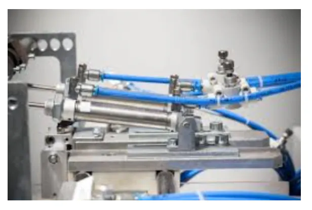
29. Pneumatic System
A pneumatic system uses compressed air to generate mechanical motion or control machine functions. A pneumatic system provides fast, safe, and reliable movement, making it ideal for tasks (clamping, actuating, or lifting machine components). Pneumatic systems are available in single-acting, double-acting, and electro-pneumatic types, each designed for specific control and force requirements. Air is directed through valves to cylinders or actuators, where air pressure is converted into controlled mechanical motion. Air pressure allows fast, repeatable operation, improves workflow efficiency, and ensures safe, consistent performance for auxiliary functions in CNC machines, automation systems, and industrial equipment through the pneumatic system.
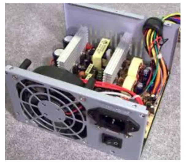
30. Power Supply Unit (PSU)
The power supply unit converts electrical energy into the appropriate voltage and current required by machine components. The power supply unit provides stable and reliable power, ensuring the safe and consistent operation of all electrical and electronic systems. Power supplies are primarily switching or linear types, often integrated with uninterruptible power supply (UPS) units to ensure backup requirements are met. The power supply unit provides regulated DC power to controllers, sensors, and logic circuits, while high-voltage power is distributed to motor drives through separate contactors or busbars.
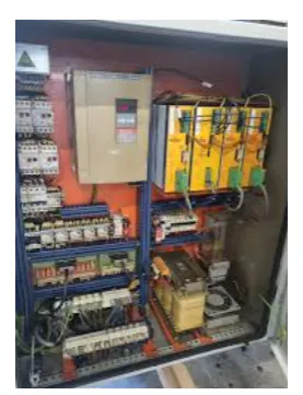
31. Electrical Cabinet
The electrical cabinet houses the electrical and electronic components of a machine, including controllers, relays, and wiring. The electrical cabinet organizes and protects electrical and electronic components, improving safety, maintainability, and overall machine reliability. Electrical cabinets come in various types (wall-mounted, free-standing, and enclosed panel cabinets), each designed for specific space, accessibility, and protection requirements. The electrical cabinet provides a controlled environment with proper wiring, terminals, and protective devices, ensuring organized electrical distribution, safeguarding components from dust, moisture, and mechanical damage, and supporting efficient troubleshooting and maintenance in CNC machines and industrial equipment.
32. CNC Controller
A CNC controller is the brain of a CNC machine, interpreting G-code and coordinating machine movements. The controller allows precise, automated machining operations and allows complex toolpaths to be executed with high repeatability and accuracy. CNC controllers come in various types, including open-loop, closed-loop, and PC-based controllers, each offering different levels of feedback, control, and processing power. The controller processes programmed instructions and sends signals to motors, actuators, and other machine devices, orchestrating their operation to ensure coordinated motion, consistent part quality, and efficient, reliable performance in automated manufacturing systems through the CNC controller.
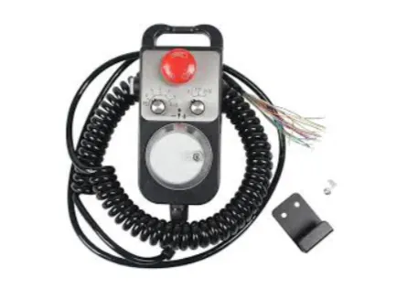
33. Handwheel (MPG)
The handwheel, called a manual pulse generator (MPG), allows direct manual control of a CNC machine’s axis movement. Handwheel supports precise positioning and fine adjustments during setup or operation, improving overall accuracy. Handwheels come in incremental and absolute types, functioning as electronic Manual Pulse Generators (MPGs) that provide different feedback levels and resolution. The device works by converting its rotation into electrical pulses that the CNC controller interprets to move the chosen axis. The handwheel enables accurate positioning, controlled incremental movement, and smoother manual operation or calibration.
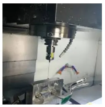
34. Probing System
A probing system is a sensor device that improves machining accuracy, reduces setup time, and enables automated inspections, supporting high-precision manufacturing. Probing systems are available in various types (touch probes, laser probes, and optical probes), each suited to specific measurement requirements and levels of precision. The probe either contacts or scans the workpiece and sends signals to the Computer Numeric Control (CNC) controller, allowing it to determine exact locations, dimensions, or surface characteristics. Probing system information ensures accurate machining, supports quality control, and allows automated adjustments for consistent, high-quality production.
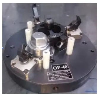
35. Workholding Fixture
A workholding fixture is a device that secures the workpiece in place during machining operations. A workholding fixture ensures stability, precision, and repeatability while minimizing vibration, which is critical for achieving high-quality cuts and surface finishes. Fixtures come in various types (vise fixtures, clamp fixtures, and custom-machined fixtures), each designed to accommodate different workpiece shapes and machining requirements. The fixture grips the workpiece securely and aligns it with the machine axes, providing a stable platform for cutting, shaping, or drilling. Workholding fixtures secure components in the correct position, enhancing machining accuracy, minimizing errors, and supporting efficient, reliable production processes.
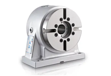
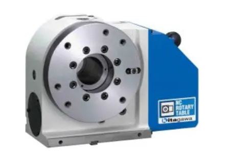
36. Rotary Table (4th Axis)
A rotary table (4th axis) is an additional machine axis that rotates the workpiece around a horizontal or vertical axis. The 4th axis improves multi-axis machining, allowing angular cuts and the creation of complex geometries that are not possible using only the standard X, Y, and Z axes. Rotary tables come in manual, Computer Numeric Control (CNC), and tilting configurations, each suited for different levels of automation, precision, and flexibility.
The table rotates the workpiece under controller commands, providing additional machining angles and positioning options. Controlled rotation improves production efficiency and enables intricate, accurate part manufacturing in CNC machining operations through the rotary table.
37. 5th Axis Trunnion
A 5th-axis trunnion is a specialized cradle or yoke mechanism that provides a tilting A-axis or B-axis, often supporting a rotary C-axis table, to allow simultaneous 5-axis machining. The 5th-axis trunnion allows complex parts to be machined in a single setup, improving accuracy, reducing setup time, and improving overall efficiency. Trunnions are available in various types, including tilting trunnion tables, CNC 5-axis trunnions, and high-speed trunnions, each designed for different precision, speed, and load requirements. The trunnion rotates and tilts the workpiece according to controller commands, providing access to multiple surfaces without the need for repositioning. The 5th axis trunnion capability enables intricate geometries, reduces errors from multiple setups, and supports high-precision manufacturing in aerospace, automotive, and mold-making applications.
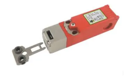
38. Safety Interlock System
A safety interlock system is designed to prevent machine operation under unsafe conditions. Safety interlock system protects operators, prevents accidents, and ensures compliance with safety standards in industrial and Computer Numerical Control (CNC) environments. Safety interlocks come in various types, including door interlocks, electrical interlocks, and mechanical interlocks, each tailored to specific machine configurations and safety requirements. The system uses sensors to identify unsafe conditions (open doors, missing guards, or misaligned components) and stops the machine from operating until the issue is resolved. Interlock systems improve operator protection, reduce the risk of equipment damage, and support adherence to workplace safety regulations through safety interlock systems by providing reliable safety enforcement.
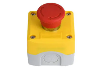
39. Emergency Stop Button
An emergency stop button is a safety device that immediately halts machine operation in emergencies. The emergency stop button protects operators, prevents accidents, and minimizes damage to machines or workpieces. Emergency stop buttons are typically mushroom-head push buttons available in twist-to-release, pull-to-release, or keyed-reset configurations to meet specific security and safety requirements. Pressing the button interrupts power or control signals to the machine, stopping all functions until the system is safely reset. Emergency stop buttons ensure quick response to hazards, improve workplace safety, and reduce the risk of injury or equipment damage in industrial and CNC environments.
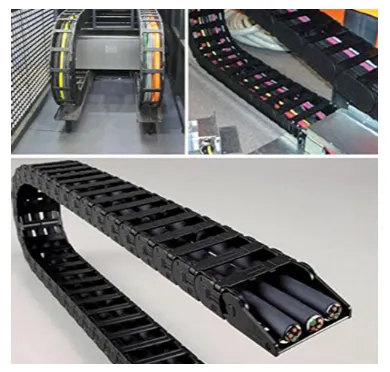
40. Cable Carrier (Drag Chain)
A cable carrier, or drag chain, is a device that organizes and protects cables and hoses on moving machine parts. The cable carrier prevents cable wear, tangling, and damage, ensuring reliable and uninterrupted machine operation.prevents cable wear, tangling, and damage, ensuring reliable and uninterrupted machine operation. Cable carriers come in various types (plastic, steel, and flexible chain carriers), each designed for different load capacities, durability, and motion requirements. Cables and hoses are routed inside the carrier, which moves along with the machine axes while maintaining proper bend radius and preventing interference. Cable carriers improve machine lifespan, lower maintenance requirements, and promote safe, efficient operation in CNC machines and automated industrial equipment by organizing and shielding wires and hoses.
How to Upgrade CNC Machine Parts
To upgrade CNC machine parts, there are six steps to follow. First, the technician evaluates the current performance of the machine to identify bottlenecks in the production cycle. Air pressure allows fast, repeatable operation, improves workflow efficiency, and ensures safe, consistent performance for auxiliary functions in CNC machines. Third, the maintenance team disconnects the power and removes the old hardware carefully to avoid damaging the surrounding circuitry. Fourth, the installer mounts the new components and ensures mechanical alignments meet the original manufacturer specifications. Fifth, the software engineer updates the controller parameters to recognize the improved hardware and optimize the motion control algorithms. Lastly, the operator runs a series of test programs and calibration routines to verify the accuracy of the upgraded CNC machine parts.
How to Design CNC Machine Parts
To design CNC Machine Parts, there are six steps to follow. First, establish functional requirements, load conditions, operating environment, and tolerance limits to ensure dimensional accuracy during CNC machining. Second, define process planning parameters that determine machining strategy, feature orientation, and tool path efficiency to support structural rigidity and material removal performance. Third, select materials that align with mechanical strength, thermal stability, and surface finish requirements, with machining demands. Fourth, optimize feature geometry to improve tool accessibility, chip evacuation, and part stability while maintaining achievable tolerance ranges. Fifth, perform design validation through CAD modeling, simulation analysis, and interference evaluation to reduce machining risk and production inefficiency. Lastly, Xometry provides CNC machining services (rapid prototyping, custom part production, and design) for manufacturability consultation to support efficient development. Xometry allows calable production and consistent quality control through digital manufacturing infrastructure, making xometry a reliable resource for CNC machine part design and manufacturing.
What Are the Advantages of Using a CNC Machine?
The advantages of using a CNC machine are listed below.
- Precision: CNC machines deliver highly accurate cuts and dimensions, ensuring consistent quality across manufactured parts.
- Repeatability: CNC machining ensures precise and consistent production of identical parts, allowing for high-volume manufacturing with minimal variation between each piece.
- Efficiency: Automated operations reduce the time required for manual setup and adjustment, allowing faster production cycles.
- Complex Machining: CNC machines perform intricate designs and complex geometries that are difficult to achieve manually.
- Reduced Human Error: Automation minimizes operator mistakes, leading to fewer defective parts and reduced material waste.
- Flexibility: Machines are reprogrammed quickly for new products or modifications, allowing adaptation to different production needs.
- Continuous Operation: CNC machines operate continuously without fatigue, supporting high-volume manufacturing.
- Integration with CAD/CAM: Direct integration with design software allows precise translation from digital models to physical components.
- Improved Safety: Operators are less exposed to cutting tools or dangerous machining processes since machines operate automatically.
- Cost Savings: CNC machines reduce labor costs, material waste, and production time over the long term, although initial investment is high.
What Are the Disadvantages of Using a CNC Machine?
The disadvantages of using a CNC machine are listed below.
- High Initial Cost: Investment in CNC machinery, software, and installation is substantial compared to conventional machines.
- Complex Programming: Programming requires specialized knowledge of G-code or CAM software, necessitating trained personnel.
- Maintenance Requirements: Regular maintenance and calibration are essential to maintain accuracy and performance, adding operational expenses.
- Dependence on Electricity: CNC machines require a continuous power supply, making them vulnerable to power interruptions.
- Limited Adaptability for Small Runs: High setup costs and the time required for programming and tooling make CNC machining less cost-effective for producing low volumes of parts.
- Equipment Downtime: Technical malfunctions, software errors, or mechanical failures halt production until resolved.
- Skill Gap: Skilled operators and programmers are needed, which poses hiring challenges in some regions.
- Tool Wear: High setup costs and the time required for programming and tooling make CNC machining less cost-effective for producing low volumes of parts.
- Initial Learning Curve: Operators transitioning from manual machining need time and training to operate CNC machines efficiently.
How Does a CNC Machine Work?
A Computer Numerical Control (CNC) machine works by following a sequence of digital instructions generated from a 3D model. The process begins with the creation of a design in Computer-Aided Design (CAD) software. CAD design is then processed by Computer-Aided Manufacturing (CAM) software to produce the G-code. The machine control unit reads the G-code and converts the data into command signals. Command signals are sent to motor drives, which power the servo motors, rotating the ball screws to move the axes based on encoder feedback. The feedback system constantly checks the position of the tool against the programmed coordinates. The spindle rotates the cutting tool at the specific Revolutions Per Minute (RPM) required for the material being processed. Coolant flows over the tool to manage heat and remove debris during the operation. Sensors monitor the entire process to ensure safety and quality throughout the cycle. The final product reflects the exact dimensions specified in the original digital file through the coordination of CNC machine parts.
Is CNC Machining Profitable?
Yes, Computer Numerical Control (CNC) machining is profitable because it offers a high rate of return through volume production and precision. The ability to produce complex parts with minimal waste reduces the cost per unit. High-precision industries (aerospace and medical manufacturing) pay a premium for the accuracy CNC machines provide. Shop owners scale their business by adding machines that run simultaneously under the guidance of one operator. The resale value of well-maintained equipment remains high, protecting the initial capital investment. Competitive pricing is achievable, as the machine manufactures parts more quickly than manual methods.
Efficiency in material usage further increases the profit margin on every job. Shops find that the machine pays for itself within 24 months of consistent operation. Profitability depends on maintaining the health of the CNC machine parts.
What are the types of CNC machines?
The types of CNC machines are listed in the table below.
"Manual machinists are optimal for rapid repairs (or simple one-offs) where programming overhead is unjustified. However, CNC is mandatory for designs requiring simultaneous multi-axis interpolation or the high-volume repeatability of a production run."
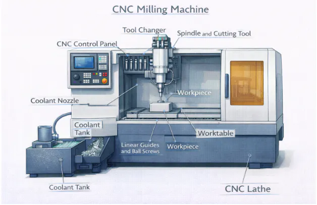
1. CNC Milling Machine
A CNC milling machine is a computer-controlled machine that removes material from a workpiece using rotary cutters, following precise G-code instructions for high-precision and complex shapes. The components include the Computer Numerical Control (CNC) controller, spindle, cutting tool, worktable, motors, ball screws, linear guides, coolant system, and optional tool changer. The machine performs cutting, drilling, slotting, engraving, and repetitive part production with minimal human intervention. Profitability depends on factors (machining precision, production flexibility, utilization rate, labor savings, and maintenance costs), making CNC milling machines efficient and potentially profitable for high-quality manufacturing.
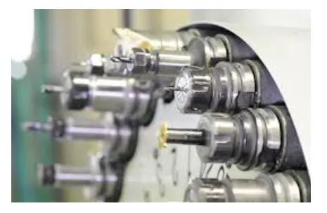
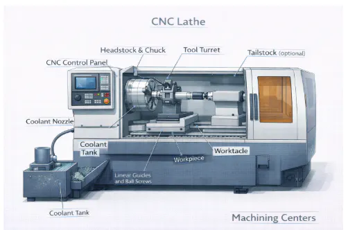
2. CNC Lathe
A CNC lathe is a computer-controlled machine for rotational machining, rotating the workpiece while a cutting tool moves along the axes to remove material, producing precise cylindrical parts. The components include the Computer Numerical Control (CNC) controller, spindle or chuck, cutting tools, tool post, turret, bed, carriage, motors and drives, lead or ball screws, tailstock, coolant system, and enclosure. CNC lathes perform turning, facing, threading, grooving, drilling, and boring operations while automating repetitive production with high accuracy and consistency. Earnings are influenced by factors (precision-driven scrap reduction, suitability for mass production, high initial investment, labor savings, and maintenance costs), making CNC lathes efficient and potentially profitable for high-volume, high-quality manufacturing
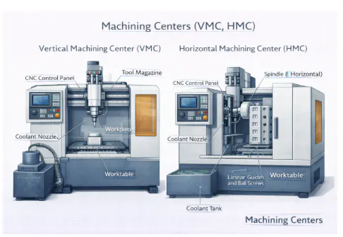
3. Machining Centers (VMC, HMC)
A machining center is a Computer Numerical Control (CNC)-controlled machine that performs multiple operations (milling, drilling, boring, and tapping) on a single setup, handling complex parts with minimal manual intervention. Vertical machining centers (VMCs) have vertically oriented spindles, ideal for flat surfaces and 3D contours, while horizontal machining centers (HMCs) have horizontal spindles, suited for high-volume, multi-sided machining. The components include the CNC controller, spindle, tool magazine or changer, worktable or rotary table, column and base, motors and drives, ball screws and linear guides, coolant system, and enclosure. Machining centers perform multi-axis operations and automate production with automatic tool changers (ATC) and, frequently in HMCs, pallet changers to provide high accuracy and repeatability. Earnings hinge on factors (efficiency, suitability for high-volume production, versatility in handling complex parts, high initial investment, and reduced labor costs), positioning machining centers as key assets for aerospace, automotive, and medical manufacturing.
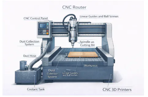
4. CNC Router
A CNC router is a computer-controlled machine used to carve, cut, engrave, or shape materials (wood, plastics, composites, aluminum, and soft metals). A CNC router operates along multiple axes (X, Y, and Z) using programmed instructions to produce precise and repeatable designs. The components include the Computer Numerical Control (CNC) controller, spindle or router head, cutting tool, worktable, gantry or bridge, motors and drives, linear guides and ball screws or rack-and-pinion drives, clamping or vacuum systems, dust collection, and optional enclosures. CNC routers cut and shape materials, engrave patterns, mill light parts, and automate repetitive production with consistent quality. Earning relies on factors (low material waste, versatility across materials and designs), moderate initial investment, reduced labor costs, and routine maintenance, positioning CNC routers as efficient and cost-effective for signage, prototypes, and small-to-medium production runs.
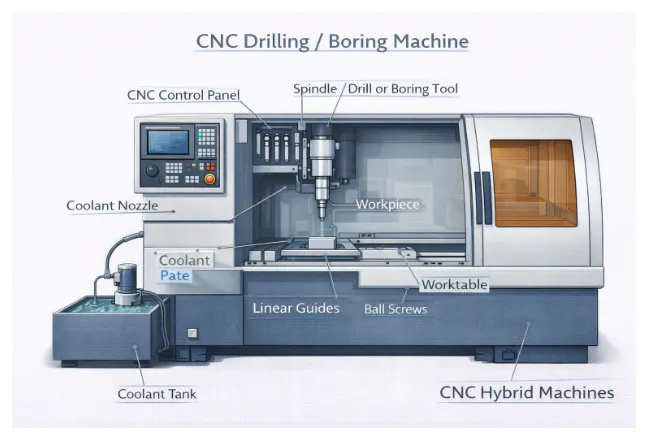
5. CNC Drilling/Boring Machine
A CNC drilling/boring machine is a computer-controlled system designed to create precise holes and enlarge existing ones in a workpiece. Drilling machines form new holes, while boring machines refine or enlarge them to tight tolerances, with Computer Numerical Control (CNC) control automating the process for speed, accuracy, and repeatability. The components include the CNC controller, spindle or chuck, cutting tools, worktable or fixture, column and base, motors and drives, linear guides and ball screws, coolant system, optional tool changer, and enclosure. The machine drills, bores, countersinks, and taps holes while automating repetitive operations for consistent high-volume production. Profitability depends on high accuracy reducing scrap, suitability for mass production, moderate to high initial investment, labor savings, and ongoing maintenance, making CNC drilling/boring machines efficient for precise, repeatable hole-making applications.
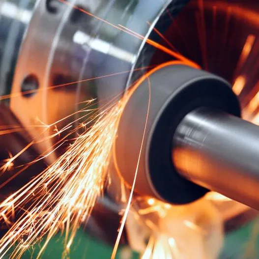
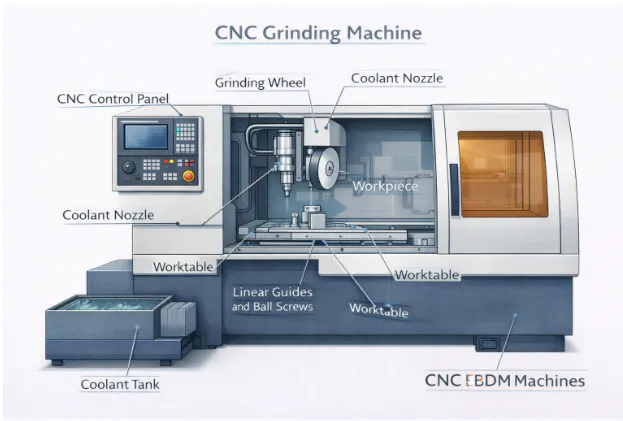
6. CNC Grinding Machine
A CNC grinding machine is a computer-controlled machine used to finish or shape workpiece surfaces by removing small amounts of material with a rotating abrasive wheel, providing high-precision surface finishes, tight tolerances, and complex geometries. The components include the Computer Numerical Control (CNC) controller, grinding wheel, spindle, worktable or fixture, column and base, motors and drives, linear guides and ball screws, coolant system, wheel dressing tool, and enclosure. CNC grinding machines perform surface and cylindrical grinding, shape complex geometries, and automate repetitive finishing operations, ensuring consistent and accurate results. Profitability depends on high precision reducing waste, important applications in aerospace and automotive industries, moderate to high initial investment, labor savings, and ongoing maintenance, making CNC grinding machines vital for high-quality, specialized manufacturing.
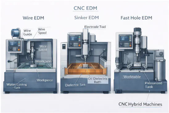
7. CNC EDM (Wire, Sinker, Fast Hole)
Electrical Discharge Machining (CNC EDM) is a computer-controlled process that removes material from electrically conductive workpieces using electrical sparks instead of traditional cutting tools, making it ideal for complex shapes, intricate cavities, and hard materials. Types of CNC Electrical Discharge Machining (EDM) include Wire EDM for precise 2D and tapered profile cutting, Sinker EDM for complex 3D molds and cavities, and Fast Hole EDM for small, deep, accurate holes.
The components include the CNC controller, power supply, electrode or wire, work tank with dielectric fluid, worktable, motors and drives, servo system, filtration system, and enclosure. CNC EDM machines cut hard materials, produce complex geometries, drill precise holes, and automate repetitive tasks with high precision and repeatability. Profitability depends on demand in mold and die making, high precision reducing scrap, the ability to machine hardened materials, specialized programming requirements, and the high initial investment, making CNC EDM essential for aerospace, automotive, and tool-making industries.
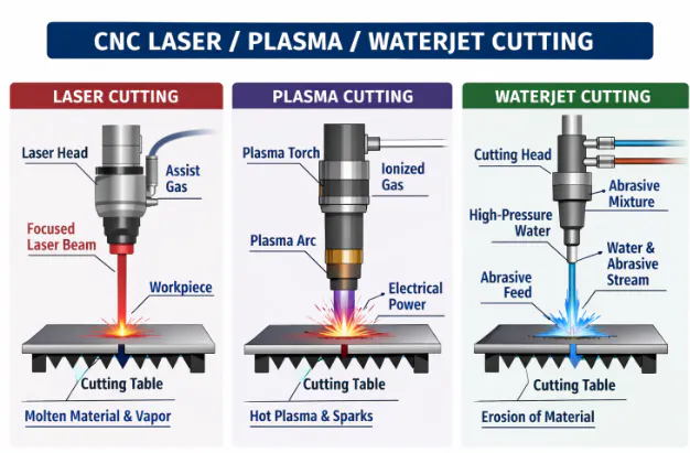
8. CNC Laser/Plasma/Waterjet Cutting
Computer Numerical Control (CNC) cutting machines use computer-controlled processes to cut, engrave, or shape materials with high precision and repeatability, employing different energy sources (lasers, plasma arcs, or high-pressure waterjets). Laser cutting is ideal for precise work on metals and plastics, plasma cutting handles thick conductive metals, and waterjet cutting slices almost any material without heat-affected zones. The components include the CNC controller, cutting head or nozzle, power or energy source, worktable, motors and drives, linear guides and ball screws or rack-and-pinion drives, assist gas or abrasive systems, and protective enclosures. CNC cutting machines create complex 2D and, in the case of multi-axis configurations, 3D shapes, process a wide variety of materials, minimize material waste, and automate repetitive operations efficiently. Earning depends on precision reducing scrap, versatility across materials, moderate to high initial investment, reduced labor costs, and ongoing maintenance, making CNC cutting machines suitable for manufacturing, prototyping, and batch production applications, including CNC Laser / Plasma / Waterjet Cutting.
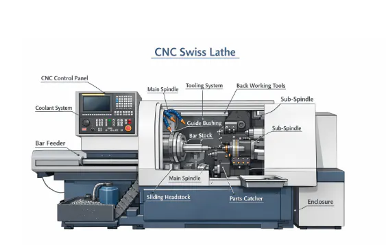
9. CNC Swiss Lathe
A Computer Numerical Control (CNC) Swiss Lathe is a computer-controlled machine designed for high-precision, small-diameter, and long workpieces, feeding material through a guide bushing to minimize deflection and vibration. The CNC Swiss Lathe is ideal for producing medical devices, watch components, electronics parts, and precision fasteners. The components include the CNC controller, main spindle, sub-spindle, guide bushing, gang tooling or turret, collet clamping system, motors and drives, linear guides and ball screws, coolant system, and enclosure. CNC Swiss lathes perform turning, threading, drilling, and milling on slender parts while automating high-volume, repetitive production with consistent accuracy. Earning depends on high precision meeting industry demand, efficiency and repeatability, reduced labor costs, high initial investment, and ongoing maintenance of guide bushings, spindles, and tooling.
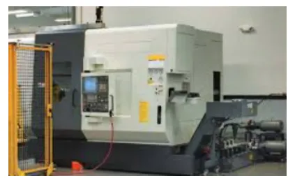
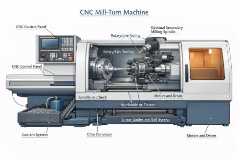
10. CNC Mill-Turn
A Computer Numerical Control (CNC) Mill-Turn Machine is a computer-controlled system that combines turning and milling operations in a single setup, allowing the workpiece to rotate like on a lathe while performing milling, drilling, and boring. The components include the CNC controller, spindle or chuck, rotary/live tooling, turret or multi-axis tool post, worktable or fixture, optional secondary milling spindle, motors and drives, linear guides and ball screws, coolant system, and enclosure. It performs combined operations, machines complex geometries, reduces setup time, and automates high-volume production with minimal operator intervention. Earning depends on improved efficiency and precision, labor savings, high initial investment, and ongoing maintenance of spindles, tooling, and linear systems, making the CNC Mill-Turn Machine ideal for producing intricate, high-quality parts efficiently.
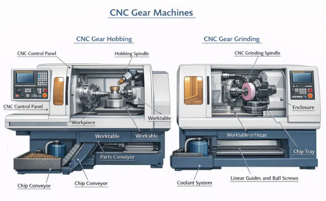
11. CNC Gear Machines
A Computer Numerical Control (CNC) gear machine is a computer-controlled system designed to manufacture gears with high precision and consistency, producing spur, helical, bevel, and worm gears through automated operations (hobbing, shaping, grinding, and cutting). The components include the CNC controller, spindle or chuck, cutting tools, tool turret or post, worktable or fixture, motors and drives, linear guides and ball screws, coolant or lubrication system, and protective enclosure. The machine cuts gear teeth with high accuracy, handles complex gear types, ensures repeatability, and automates high-volume production with minimal manual intervention. Profitability depends on reduced waste from high precision, support for mass production in industries (automotive and aerospace), lower labor costs, high initial investment, and ongoing maintenance of cutting tools, spindles, and motion systems.
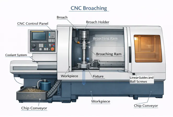
12. CNC Broaching
A Computer Numerical Control (CNC) Broaching Machine is a computer-controlled system that utilizes a multi-toothed broach tool to remove material in a single stroke, providing high-speed production of precise internal or external profiles, producing precise shapes (keyways, splines, and holes with high repeatability and minimal manual setup). The components are a CNC controller, a spindle or ram, a broach tool, a fixture or worktable, linear guides and ball screws, a coolant system, and a protective enclosure. The machine cuts internal or external profiles efficiently, removes material quickly, and automates production with minimal operator intervention. Profitability depends on extremely fast cycle times for high-volume production, though it is tempered by the high cost of part-specific custom tooling and intensive maintenance of the broach cutting edges.
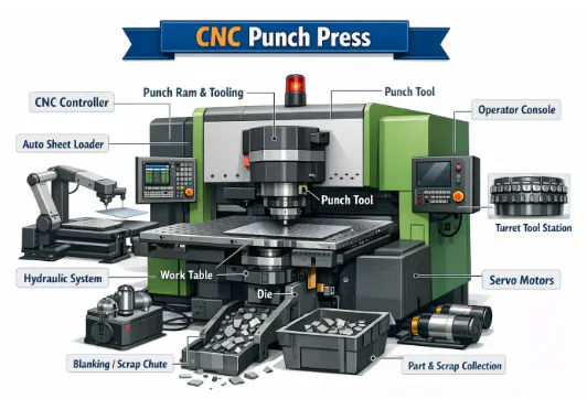
13. CNC Punch Press
A Computer Numerical Control (CNC) punch press is a computer-controlled machine that punches holes or shapes into sheet metal by selecting and actuating punches from a programmable turret or tool changer. The components are a CNC controller, a worktable or shuttle, a punch and die set, a hydraulic or mechanical ram, linear guides and ball screws or rack-and-pinion drives, and a safety enclosure. CNC Punch Press creates holes and patterns, automates sheet metal fabrication, and performs repetitive operations with minimal manual intervention. Profitability comes from high throughput, reduced labor costs, and a moderate initial investment, depending on tonnage and automation level.
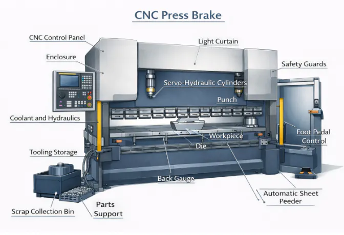
14. CNC Press Brake
A Computer Numerical Control (CNC) press brake is a computer-controlled machine that bends sheet metal precisely using a punch and die, automating forming processes for consistent angles and complex profiles. The components are a CNC controller, a hydraulic or electric ram, a CNC backgauge with ball screw drives, a punch and die set, linear guides, and safety systems (enclosures or light curtains). It produces accurate bends, reduces manual errors, and performs repetitive batch operations efficiently. Profitability comes from high precision reducing scrap, labor savings through automation, and a moderate investment depending on tonnage and level of automation, making the CNC press brake highly profitable for metal fabrication, enclosures, and chassis production.
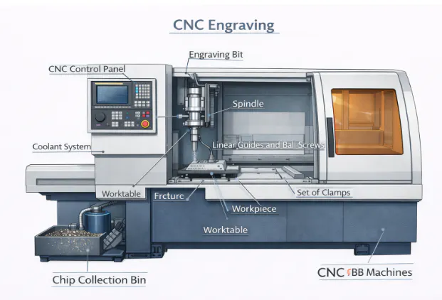
15. CNC Engraving
A Computer Numerical Control (CNC) Engraving Machine is a computer-controlled device that carves text, patterns, or designs onto materials (metals, plastics, or wood) using a rotary or laser tool. CNC engraving consists of a CNC controller, cutting tool or laser head, worktable or fixture, motors and drives, linear guides and ball screws, coolant or dust collection system, and an enclosure for safety. The machine engraves text, logos, and decorative designs with high precision, automates repetitive tasks, and ensures consistent quality. Earning comes from high-value customization, minimal material waste, and a moderate investment depending on tool type, making it ideal for signage, awards, and precision markings CNC engraving.
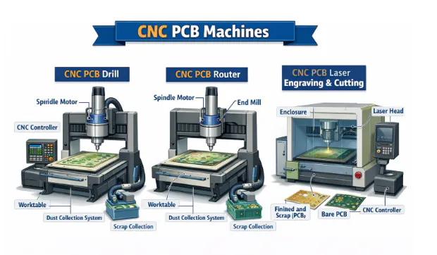
16. CNC PCB Machines
A Computer Numerical Control (CNC) Printed Circuit Board (PCB) Machine is a computer-controlled system designed to drill, mill, and route printed circuit boards with high precision. The components include a CNC controller, spindle or drill, worktable or fixture, motors and drives, linear guides and ball screws, dust extraction or vacuum system, and an enclosure for operator safety. The machine drills vias and holes, routes board outlines, performs isolation milling of copper traces, and automates production to reduce errors and manual labor. It is profitable for electronics prototyping and small-batch production due to high precision, labor savings, and a moderate investment depending on size, spindle type, and automation level, making CNC PCB Machines ideal for the industry.
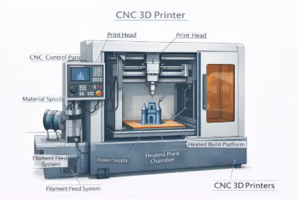
17. CNC 3D Printers
A Computer Numerical Control (CNC) 3D printer is a computer-controlled additive manufacturing machine that builds objects layer by layer from materials (plastic, resin, metal, or composites), ensuring precise geometry and repeatability. CNC 3D printer main components include a Computer Numerical Control (CNC) controller, extruder or print head, workbed or build platform, motors and drives, linear guides and ball screws, heating elements, and an enclosure for safety and environmental control. The machine performs additive manufacturing, produces prototypes, creates complex geometries, and automates production with minimal supervision. CNC 3D printer is profitable for rapid prototyping and low-waste production, offering labor savings, although investment costs vary depending on material type and printer size.
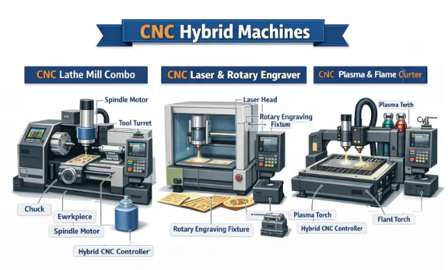
18. CNC Hybrid Machines
A CNC Hybrid Machine integrates additive manufacturing (Directed Energy Deposition) and subtractive milling/turning in a single setup, allowing for the addition of material and its subsequent precision machining without removing the part from the fixture, allowing the production of complex parts with fewer setups and higher precision. The components include a CNC controller, rotary and linear axes (spindles, turrets, and gantries), multi-function cutting/additive/laser tools, a worktable or fixture, motors and drives, linear guides and ball screws, cooling and dust management systems, and an enclosure for operator safety. The machine performs multiple operations in one setup, reduces handling and setup time, produces high-precision parts for industries (aerospace and medical), and automates production with minimal supervision. CNC hybrid machines are profitable due to high efficiency, precision, and labor savings, though they require a significant initial investment, making CNC hybrid machines highly valuable for specialized manufacturing.
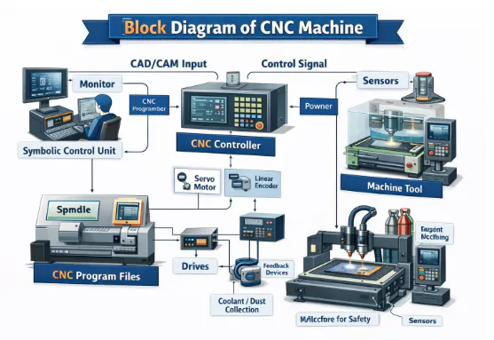
Block Diagram of CNC Machine
The block diagram of the CNC machine is shown below.
What are the main structural components of a CNC machine?
The main structural components of a CNC machine are shown in the table below.
How does the machine frame affect rigidity and accuracy?
The machine frame affects rigidity and accuracy by serving as the load-bearing structure that resists cutting forces, vibrations, and thermal distortions, ensuring geometric alignment and repeatable motion. A rigid, high-mass frame absorbs dynamic loads, maintains axis straightness and squareness, dampens chatter for better surface finish, and provides thermal stability to prevent dimensional drift. Deflection or instability is transmitted to the tool-workpiece interface, causing errors, taper, or positioning drift. Materials (cast iron, polymer concrete, or mineral casting) improve vibration damping and thermal stability. The frame’s performance directly influences spindles, linear guides, ball screws, motors, encoders, and workholding systems, making it critical for CNC milling, machining centers, grinding, Swiss lathes, EDM, high-speed, and multi-axis machines.
What is the role of the bed in CNC machine stability?
The role of the bed in Computer Numerical Control (CNC) machine stability is to provide a heavy, rigid foundation that supports the entire machine, including the workpiece, spindle, and tooling systems. The bed's wide footprint distributes loads evenly, minimizing floor-induced vibrations and preventing sagging or twisting that compromises accuracy. Internal ribbing or honeycomb structures increase stiffness without excessive weight, while thick cast walls dissipate vibrations generated during high-speed milling or cutting. The bed ensures linear guideways and ball screws remain straight and parallel, maintaining precise motion in the X and Y axes. It houses auxiliary systems (coolant tanks, chip conveyors, and electrical channels), integrating machine functions efficiently. The accuracy of multi-axis operations (in lathes, machining centers, or mill-turn machines) relies on the bed to maintain the precise spatial relationship between the spindle, turret, and worktable. Proper leveling, alignment, and maintenance of the bed are critical to ensure consistent repeatability, reduce tool wear, and maintain high-quality surface finishes across all CNC operations.
How do linear guideways influence motion precision?
Linear guideways influence motion precision by providing a low-friction, rigid path for the movement of machine axes. Linear guideways ensure that linear motion occurs in a straight line with minimal deviation, which is critical for maintaining dimensional accuracy and repeatability. Precision rolling elements, ball or roller bearings within the guideways, eliminate the stick-slip effect common in older sliding or box-way designs, allowing smooth, controlled motion under load.
High rigidity in the rails and carriages prevents deflection, tilting, or lifting of the axis during heavy cutting operations, while preloading removes clearance, further increasing motion accuracy. High rigidity in the rails and carriages allows servo or stepper motors to achieve extremely fine positioning, down to 0.0001 inches (2 to 3 microns). Smooth guideway motion reduces backlash, vibration, and chatter, improving surface finish and tool life.
Regular lubrication is essential to maintain low friction, prevent wear, and dissipate heat generated during high-speed movement. Thermal expansion of the rails affects precision, so temperature-controlled environments or thermally stable materials are used for high-end Computer Numerical Control (CNC) machines. Over time, wear and the buildup of debris in the guideways cause most of the loss in accuracy and repeatability in older CNC machines.”
Linear guideways are critical for high-speed machining, complex 3D toolpaths, and multi-axis operations in milling centers, grinding machines, Swiss lathes, and 5-axis machines. Proper maintenance, alignment, and periodic replacement of guideways are essential for preserving long-term machine precision.
What is the function of ball screws in the structure?
The function of ball screws in the structure is to convert rotary motion from motors into precise linear motion along Computer Numerical Control (CNC) axes. A ball screw consists of a threaded shaft and a nut with recirculating ball bearings, replacing sliding friction with rolling friction for high efficiency and smooth motion. Preloaded nuts minimize backlash, ensuring accurate positioning, while the screw’s pitch determines axis resolution and speed. Ball screws provide the thrust necessary to drive cutting tools through hard materials.
High-precision ball screws are ground or rolled to tight tolerances, and designs include cooling or lubrication systems to reduce thermal expansion during long cycles. Wear, misalignment, or failure causes lost motion, positioning errors, or chatter at the tool–workpiece interface. Ball screws are critical for high repeatability, smooth acceleration, and multi-axis coordination in milling centers, lathes, and 5-axis machines. Regular maintenance and lubrication are important to maintain accuracy and machine performance.
How does spindle housing impact vibration control?
Spindle housing impacts vibration control by providing a rigid, stable enclosure for the spindle motor and high-speed bearings. A heavy and precise housing absorbs centrifugal and cutting forces generated by tools rotating at high Revolutions Per Minute (RPMs), reducing radial and axial runout. Excessive vibration in the spindle causes chatter, poor surface finish, and accelerated tool wear. Housings incorporate cooling jackets or channels to manage heat. preventing thermal expansion that shifts the tool position. Designs include damping materials to suppress resonance and reduce noise. Properly engineered spindle housings maintain rigidity under aggressive roughing or high-speed operations, ensuring consistent tool-to-workpiece contact. A lightweight or poorly fitted housing amplifies vibration at certain frequencies, degrading precision and surface quality. The spindle housing is critical for machine stability, repeatability, and the performance of high-speed Computer Numerical Control (CNC) operations in milling centers, lathes, and multi-axis machines.
What is the purpose of the column in CNC machine design?
The purpose of the column in Computer Numerical Control (CNC) machine design is to provide the vertical structure that supports the spindle head and Z-axis motion. CNC Machine design must be highly rigid to resist cutting forces during vertical milling and drilling, preventing flexing that affects precision. The column’s height determines maximum workpiece clearance, while its perpendicular alignment to the bed ensures squareness in finished parts. Internal reinforcements and precision surfaces maintain stability, guiding the Z-axis with minimal deflection. The mass of the column contributes to vibration damping, improving surface finish and tool life. Columns are made from cast iron or mineral casting to improve rigidity and thermal stability, minimizing expansion during prolonged operations. The column supports vertical motion and works with guideways, ball screws, and the spindle assembly, forming a key structural component that ensures accuracy, repeatability, and overall CNC machine performance.
How do gantry and bridge structures differ?
Gantry and bridge structures differ by the machine components that are supported and move.
In a gantry design, the overhead beam travels along rails on both sides of the machine, while the worktable stays in place.
Gantry and bridge structures design provides an open work area, which is ideal for large-format CNC routers, plasma cutters, or woodworking machines. Gantry systems arescaled to huge sizes, but the moving beam requires precise dual-drive synchronization to prevent racking or misalignment during motion.
By contrast, a bridge design features a stationary overhead beam, with the worktable moving underneath.
The fixed overhead beam design of the bridge structure provides higher rigidity and stability, making it suitable for high-precision milling of heavy parts or metals. Bridge machines offer better vibration damping, which improves surface finish and tool life. The choice between gantry and bridge depends on workpiece size, weight, machining requirements, and the balance between accessibility and rigidity. The structures aim to provide accurate, repeatable X and Y axis motion.
How does machine geometry affect tolerance capability?
Machine geometry affects tolerance capability by determining how accurately the machine axes are aligned and move relative to each other. If the X, Y, and Z axes are not exactly perpendicular or parallel, the parts may show distorted dimensions, angular inaccuracies, or tapering.
Deviations (pitch, roll, and yaw in axis) translate into dimensional inaccuracies on the workpiece. The flatness of the table, squareness of the spindle to the Z-axis, and parallelism of the guideways are critical for maintaining tight tolerances. Thermal expansion, foundation shifts, and wear on linear rails or ball screws degrade geometry. Laser interferometers and precision calibration tools are used to measure and correct geometric errors. The highest-quality controllers cannot compensate for poor machine geometry, so structural precision is fundamental. Maintaining geometric stability ensures consistent part accuracy, repeatability, and the ability to achieve tight engineering tolerances across high-volume production.
What materials are used for CNC machine frames?
Materials used for Computer Numerical Control (CNC) machine frames are grey cast iron, ductile iron, structural steel, polymer concrete, and aluminum. The materials are used in determining rigidity, vibration damping, and thermal stability. Grey cast iron is used for its excellent vibration absorption, cost-effectiveness, and wear resistance. Ductile iron offers higher strength and impact resistance, which is suitable for heavily loaded components. Polymer concrete or mineral casting is favored in high-speed machining due to its superior vibration damping, ten times better than cast iron. Aluminum is used for moving gantries in routers, reducing weight and improving acceleration. Structural steel is employed in large, welded-frame machines where casting is impractical. Each material presents a trade-off between stiffness, weight, and thermal expansion. Proper selection ensures that the frame resists cutting forces, maintains axis alignment, and minimizes thermal distortion, all of which are crucial for accuracy, surface finish, and repeatability in CNC machining. Material choice directly impacts machine performance and longevity.
How does thermal deformation affect CNC structure?
Thermal deformation affects Computer Numerical Control (CNC) structure by causing expansion of machine components due to heat generated by motors, bearings, cutting friction, and ambient temperature fluctuations. Expansion of machine components caused by heat shifts the position of the tool relative to the workpiece, leading to dimensional errors and reduced tolerance accuracy. The spindle is sensitive, elongating as it warms, while linear guideways and ball screws expand, potentially causing binding or loss of precision in axis motion. Non-controlled environments exacerbate thermal deformation effects, introducing uneven geometric changes throughout the day. Modern CNC machines employ thermal compensation software that adjusts coordinates based on temperature sensor data to maintain dimensional accuracy and counteract tool-tip drift. Symmetrical machine designs help ensure expansion occurs uniformly, minimizing distortion. Active cooling systems for spindles, ball screws, and motors stabilize temperatures during prolonged operations. Proper heat management is important for maintaining repeatability, surface finish, and part accuracy. Controlling thermal deformation is a critical factor in the design and performance of high-precision CNC machine parts.
What is structural damping in CNC machines?
The structural damping in Computer Numerical Control (CNC) machines is the machine’s ability to absorb and dissipate mechanical energy, reducing vibrations during operation. High damping prevents resonance at specific frequencies, which causes chatter marks on the workpiece, reduces surface finish quality, and accelerates tool wear. Materials (cast iron) provide natural damping due to graphite flakes within their structure, while polymer concrete and mineral castings achieve even higher damping for ultra-precision applications. Advanced machines incorporate active damping systems, where sensors and actuators counteract vibrations in real-time. The mass and design of the bed, column, and frame improve damping, allowing the machine to maintain stability during heavy or high-speed cutting. Machines with inadequate damping require slower feed rates and reduced depth of cut to avoid oscillations. Effective structural damping is critical for maintaining dimensional accuracy, prolonging tool life, and ensuring consistent performance of CNC machine parts in demanding production environments.
How does machine mass influence cutting performance?
Machine mass influences cutting performance by providing the inertia necessary to resist forces generated during machining. A heavier Computer Numerical Control (CNC) machine remains stable during aggressive roughing and high-load cutting, reducing deflection and improving dimensional accuracy. Mass helps absorb vibrations caused when the cutting tool engages or exits the material, improving surface finish and tool life. The weight of the base and column stabilizes the machine during rapid axis accelerations while supporting larger workpieces without flexing. Excessive mass in moving components (table or saddle) limits acceleration and reduces responsiveness, so engineers carefully balance stationary mass with lightweight moving parts. Proper mass distribution optimizes the center of gravity, reduces chatter, and improves dynamic stability. A high mass-to-power ratio is beneficial for heavy-duty milling, ensuring precision under high cutting forces. Machine mass is a fundamental factor influencing vibration damping, cutting stability, and the consistent performance of CNC machine parts.
What is the difference between box way and linear way structures?
The difference between box way and linear way structures is in the design and function of their bearing surfaces. Box ways use broad, flat sliding surfaces that create maximum contact area between the moving parts and the guideways, providing exceptional rigidity and vibration damping. Broad, flat sliding surfaces of box ways that create maximum contact area, rigidity, and vibration damping make them ideal for heavy-duty machining, high cutting forces, and applications where structural stiffness is critical. Linear ways rely on recirculating ball or roller bearings running along precision rails, producing low friction and smooth motion. A low-friction, smooth motion is produced by linear ways using recirculating ball or roller bearings, allowing for faster, rapid traverse speeds, higher acceleration, and improved efficiency in medium- to light-duty operations. Box ways require continuous lubrication and are prone to wear over time, while linear ways are easier to maintain or replace and maintain high precision over long periods. The choice depends on the machine’s purpose: linear ways dominate modern high-speed milling centers, while box ways are preferred in heavy-duty lathes, boring mills, and large CNC machining centers for maximum load capacity.
How does structural alignment affect repeatability?
Structural alignment affects repeatability by ensuring that the axes of a Computer Numerical Control (CNC) machine return to the same position consistently. Misaligned components create uneven drag, friction, or binding, which prevents servo motors from settling precisely at the commanded coordinates. Proper alignment of ball screws, linear guideways, and spindles is critical to maintain smooth, consistent motion. Even minor structural changes from foundation settling, uneven leveling pads, or worn parts can lead to large deviations in repeated movements.
Thermal expansion caused by motors working against misaligned axes further exacerbates position drift. High repeatability is important for producing large volumes of identical parts with minimal dimensional variation. Well-aligned, high-precision machines can achieve repeatability within 0.0001 to 0.0002 inches (2.5 to 5 µm), with specialized ultra-precision equipment reaching 1.27 µm or less. Regular inspections and adjustments to maintain squareness, flatness, and parallelism are necessary to preserve structural integrity. Repeatable precision depends on the alignment of load-bearing and motion-critical CNC machine parts.
What is the difference between CNC machining and manual machining?
The difference between CNC machining and manual machining is in control method, automation, and precision. Manual machining relies on a skilled operator to move handwheels and guide the cutting tool along the workpiece. Computer Numerical Control (CNC) machining uses a computer to execute pre-programmed instructions, moving multiple axes simultaneously with exact repeatability. CNC allows complex geometries and multi-axis operations that are extremely difficult or impossible to do manually. Consistency and accuracy are higher in CNC, however, while computers do not fatigue, they will precisely execute incorrect programming or setup data provided by the human operator. Manual machining is suitable for simple, one-off parts, repairs, or low-volume work where programming is not justified. CNC machines require greater upfront investment but reduce labor and cost per part in high-volume production. The skill set differs: CNC operators need knowledge of Computer-Aided Design/Computer-Aided Manufacturing (CAD/CAM) programming and G-code, while manual machinists rely on physical dexterity and experience. Advanced CNC machine parts allow superior precision, surface finish, and repeatability compared to manual methods.
Disclaimer
The content appearing on this webpage is for informational purposes only. Xometry makes no representation or warranty of any kind, be it expressed or implied, as to the accuracy, completeness, or validity of the information. Any performance parameters, geometric tolerances, specific design features, quality and types of materials, or processes should not be inferred to represent what will be delivered by third-party suppliers or manufacturers through Xometry’s network. Buyers seeking quotes for parts are responsible for defining the specific requirements for those parts. Please refer to our terms and conditions for more information.