7 Steps on How to Create DXF Files for Laser Cutting


In this article, we learn how to create DXF files in seven simple steps.


When it comes to laser cutting, DXF (Drawing Exchange Format or Drawing Interchange Format) is among the most common file formats alongside SVG (Scalable Vector Graphics). It feeds vectors to laser cutting machines, which turn the designs into cutting instructions. DXF is an open-source file type, which means that you can use a whole variety of software to create vectors. Inkscape® is free to use and is what we’ll be using for this article on the seven steps to create DXF files for laser cutting.
1. Select an Image for DXF File
The initial step is to find the image you want to use, and it can be in any format. But the images that tend to work best have strong outlines. In our example, we’re using the mortarboard shown in the image below:

Black mortarboard.

Gap in Mortarboard
If we were to upload the image into Inkscape like this, we’d have two problems to deal with. Firstly, the software will register this as two separate pieces and cut them out accordingly, which isn’t what we want. Secondly, even if that’s what we wanted, the lines are close enough to potentially cause the material to warp. So, the way to fix this is to remove the gap before inputting the image into Inkscape. Here’s how we edited it:

Edited Mortarboard
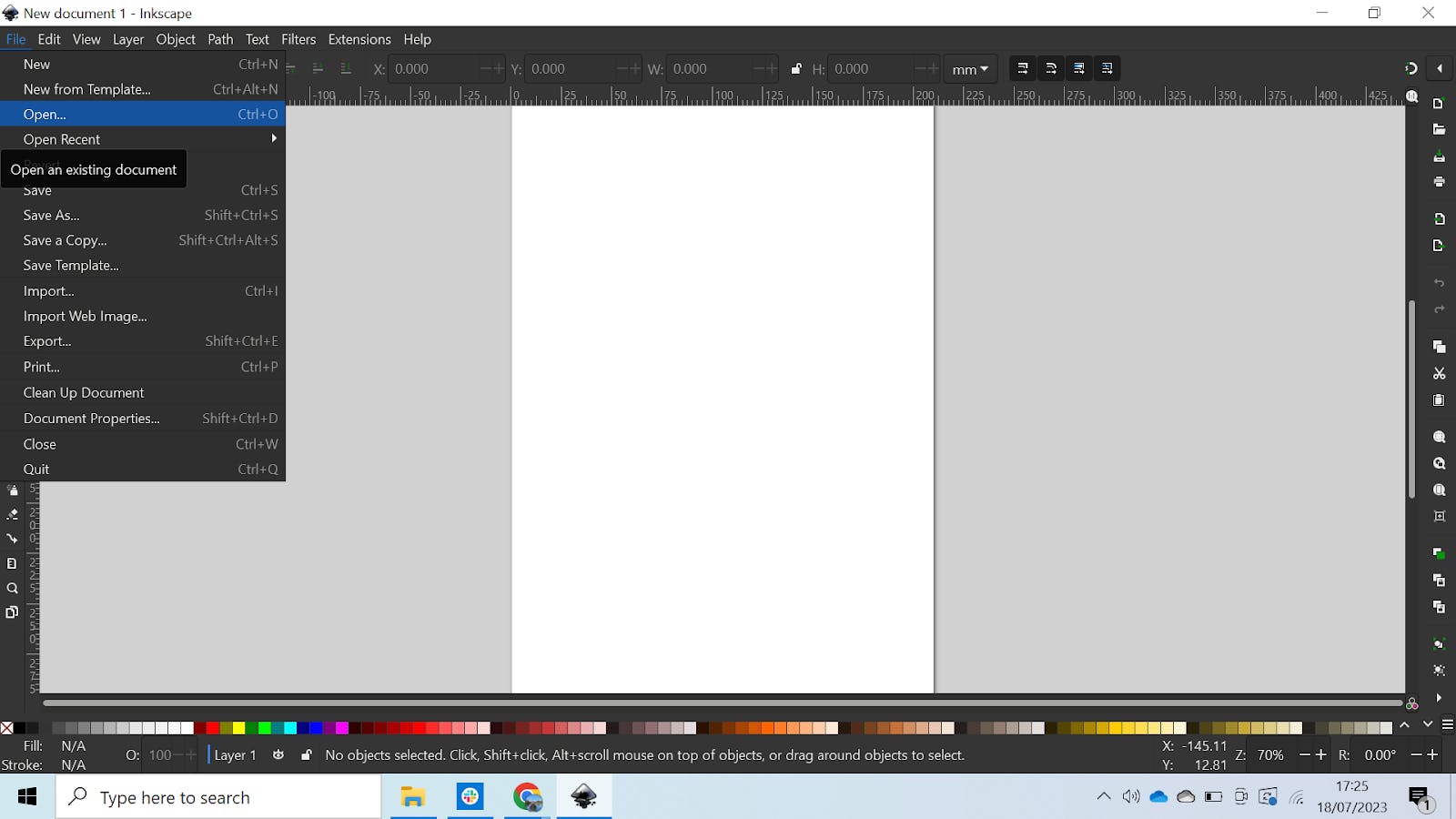
Inkscape Canvas
This will open a window that allows you to pick the image you want to import. Select it, and click “Open” like so:
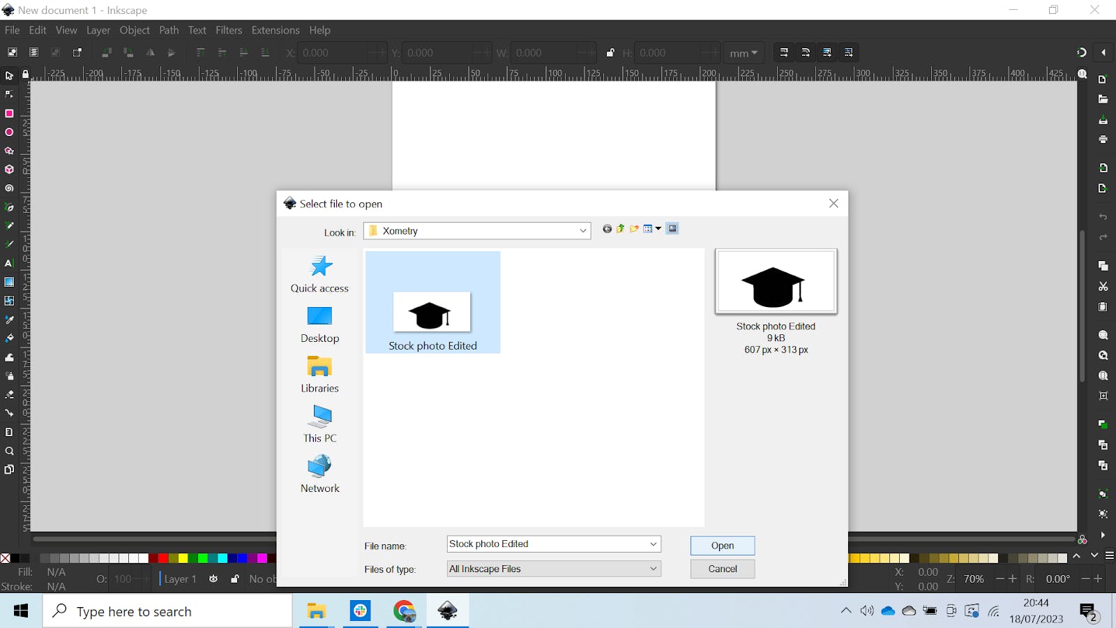
Inkscape Open Folder
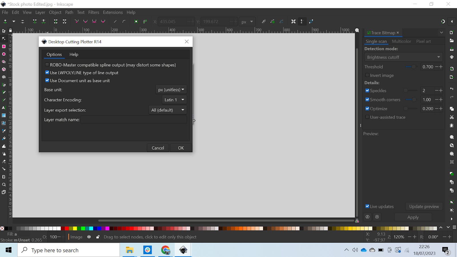
A box will appear that allows you to change the image settings, but you can leave these as standard and go ahead and click “Ok” as shown below:
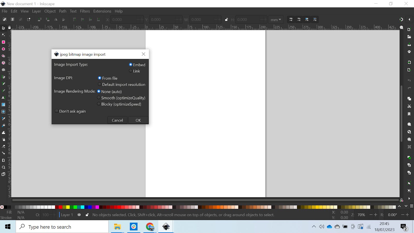
Inkscape Dialog Box
Your image should now be imported into Inkscape and look something like this:
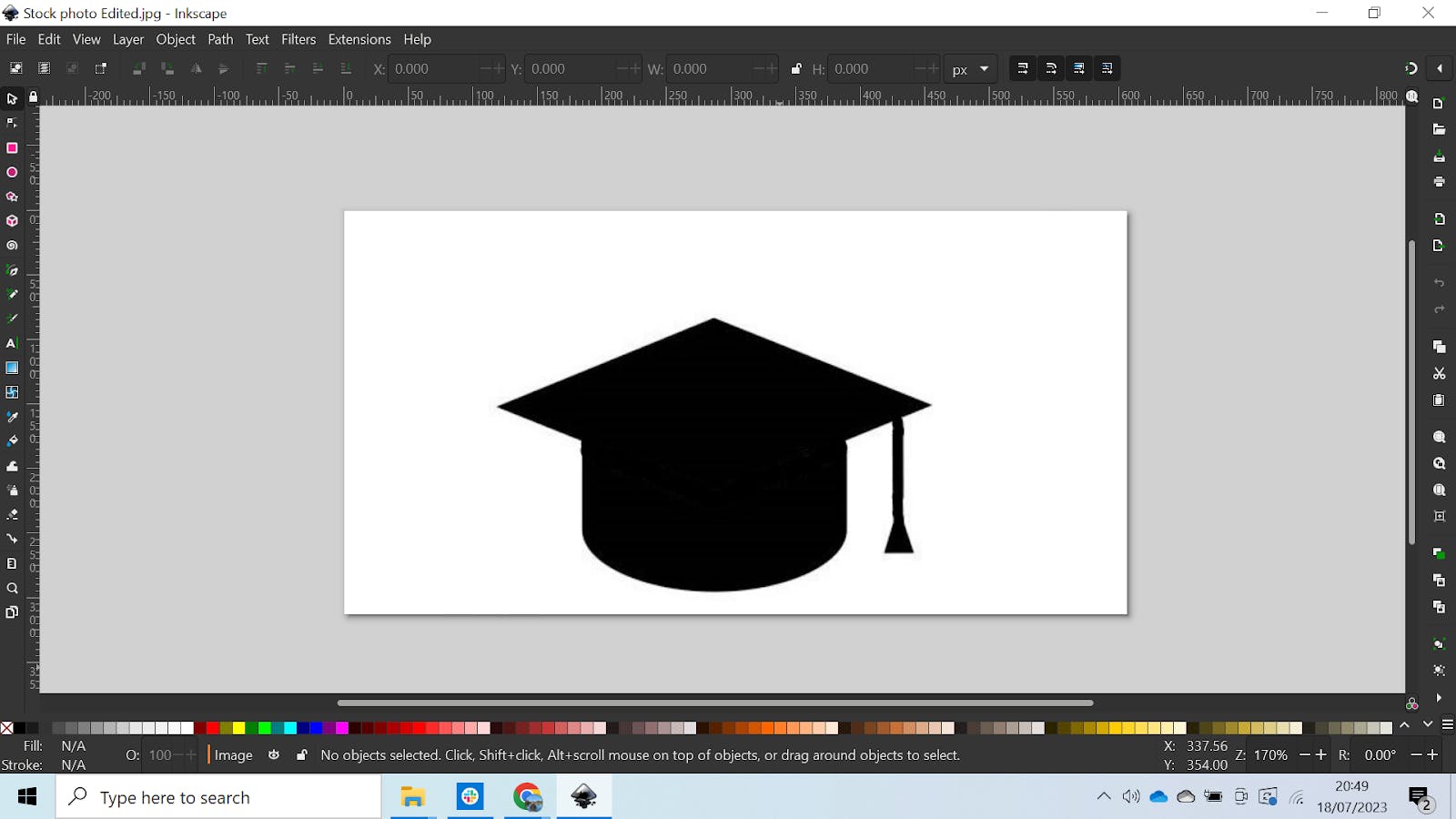
Mortarboard in Inkscape
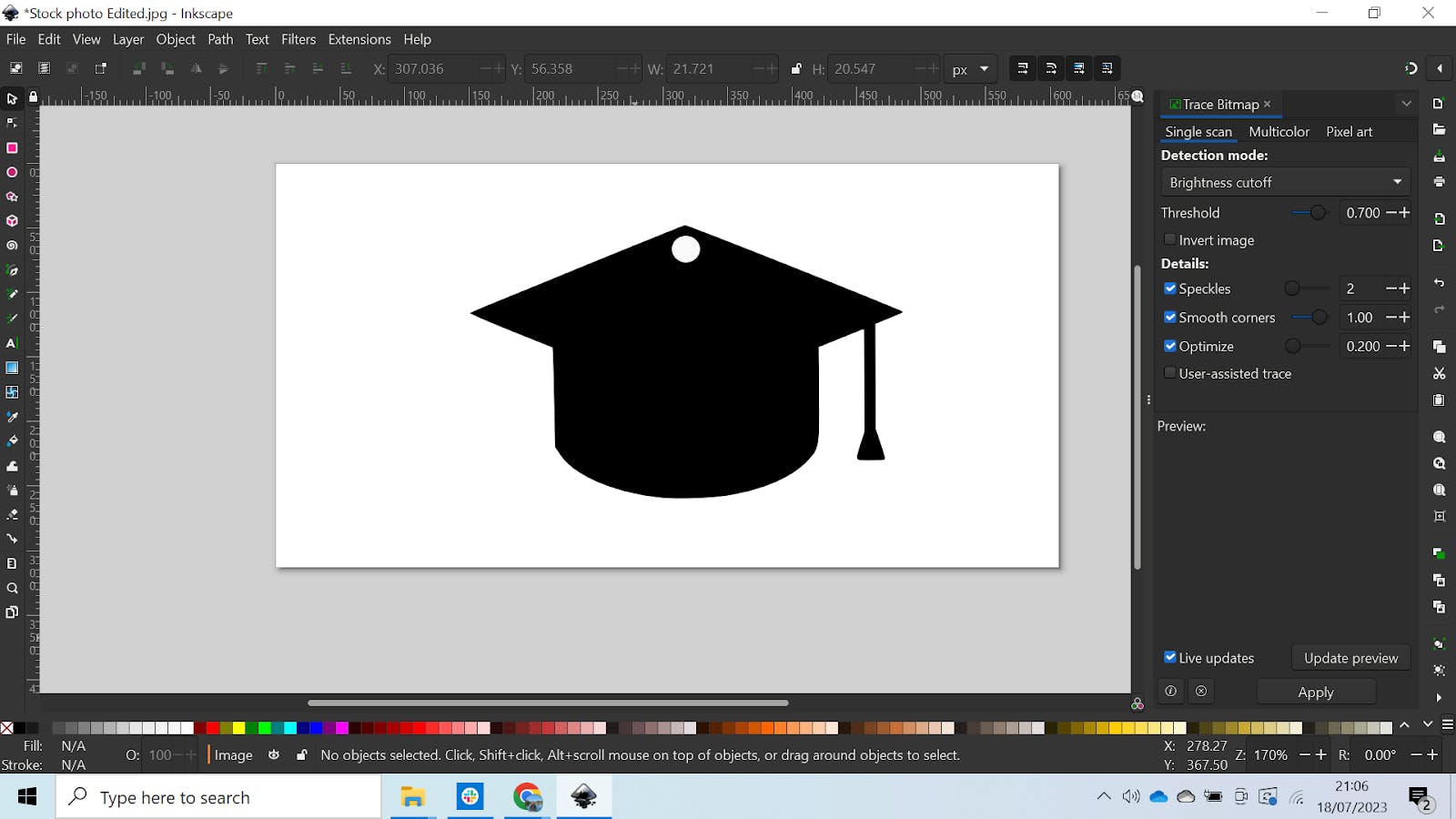
To trace the bitmap, select Path > Trace Bitmap. It should look like this:
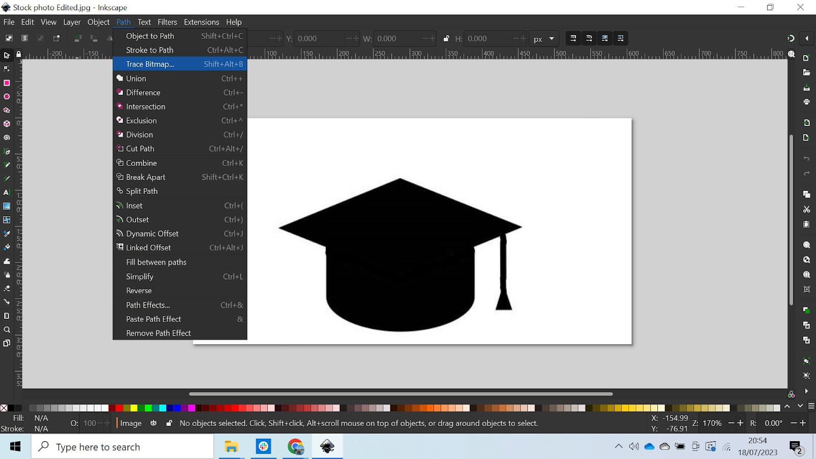
Trace Bitmap
You’ll see a Bitmap menu appear on the right, which gives you further options. The point of this is to trace the silhouette and create a line for the laser cutter. Your screen should look a little something like this:
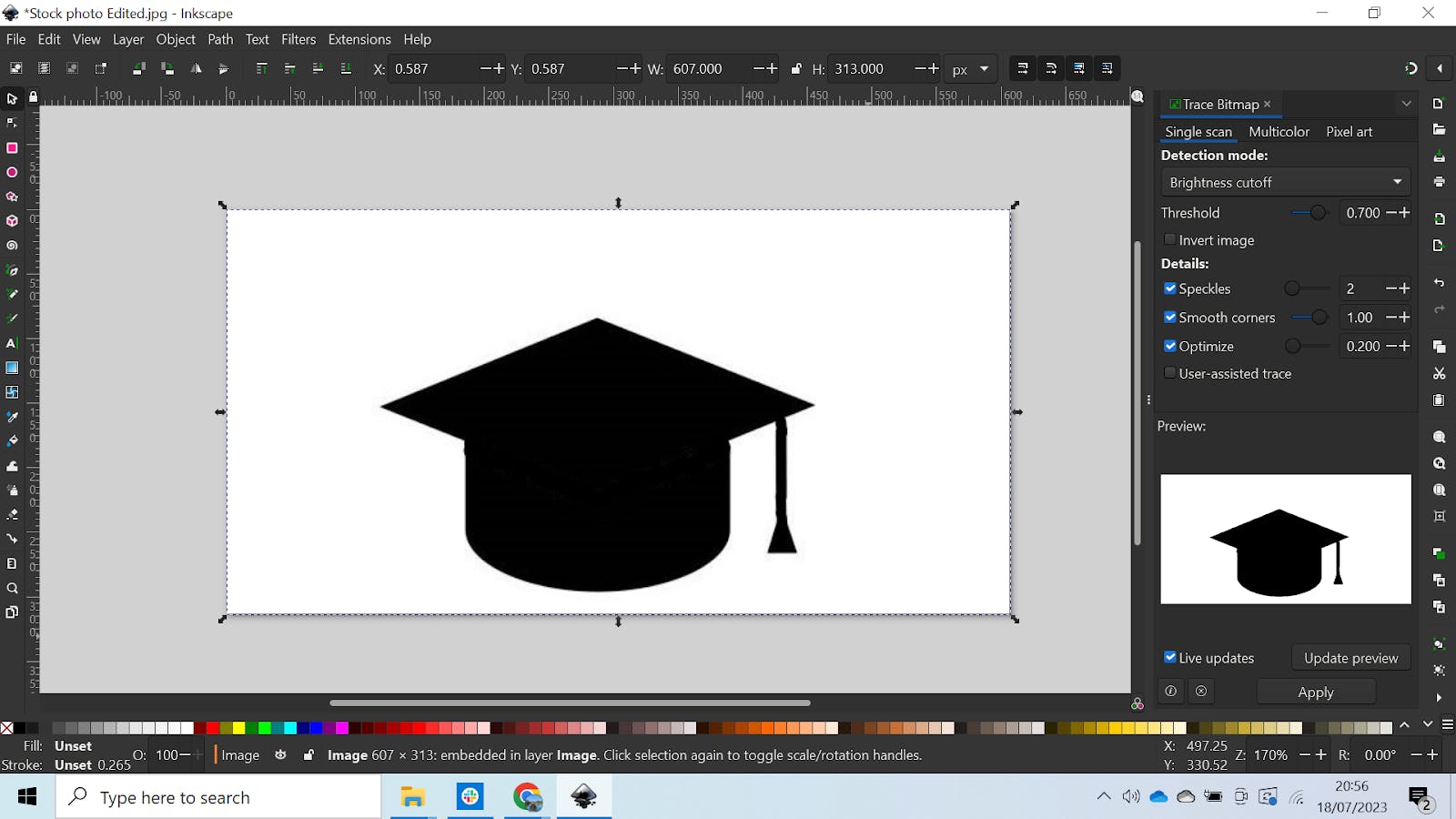
Trace Bitmap Applied
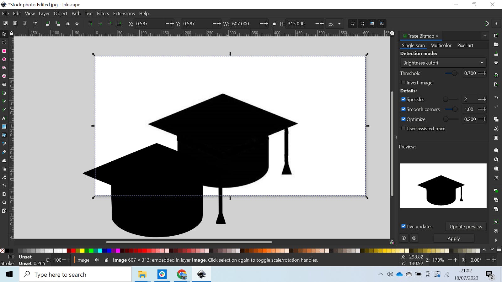
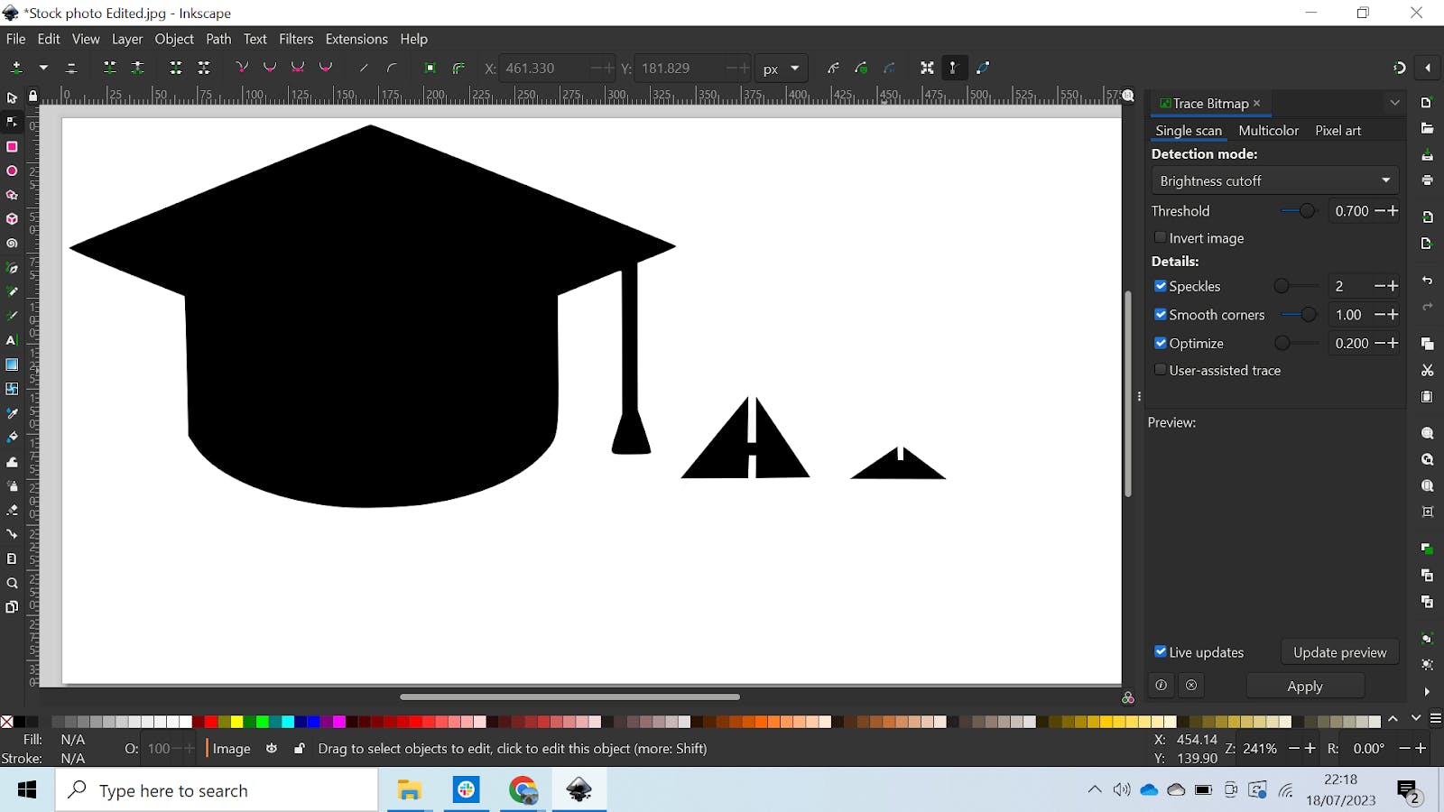
Make sure you select the image for this to work and click on “Apply.” When it’s done its thing, the silhouette will appear on top of the image like so:
Delete the Original Photo
Move the new silhouette to the side, and delete the original. Then you’ll just be left with the new image as shown below:
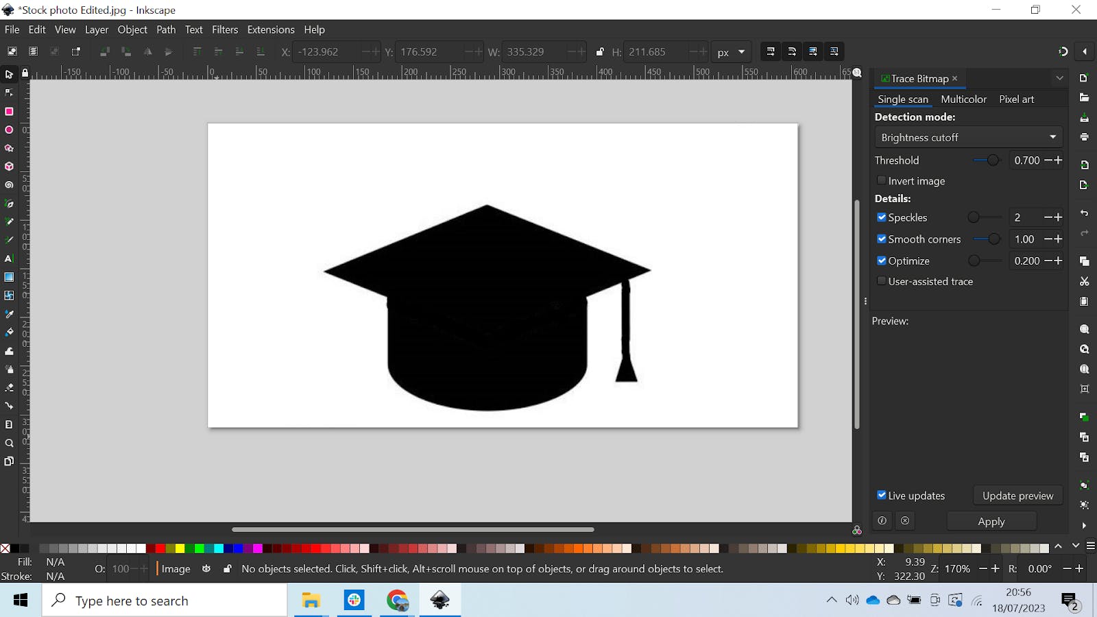
Silhouette
Hanging Hole Edition
To make one yourself, use the circle tool on the toolbar on the left, and hold Ctrl + Alt while drawing to make a perfect circle. If you want to make a base, though, you can draw the additional parts like this:
Base Edition
5. Making Page Orientation Changes To Enclose Base Design
When the software has mapped out and traced your image, it’s likely that it won’t all fit on the page, but don’t worry because it’s an easy fix. Select all the pictures and go to File > Document Properties. In the box that pops up (shown in the next image), click on “Resize to content.” That will make the page fit to your design and save scrap.
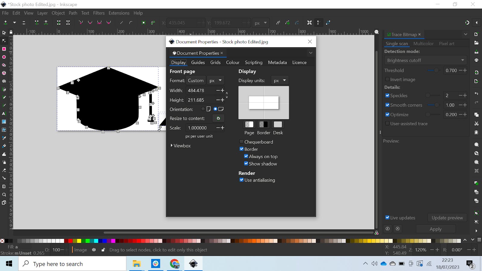
Resize Document To Fit Geometry
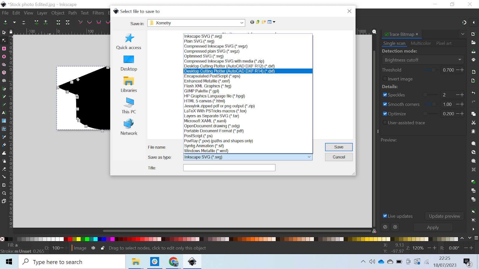
Save the File as DXF
When the dialog box pops up, go ahead and click “Ok” like so:
Click “Ok” in the Dialog Box
7. Importing the DXF File, Choosing the Speed, and Choosing the Power Settings
Import the DXF file into your laser cutting software, and take your time choosing the speed and power based on what the manufacturer recommends for the material and thickness you’re using. Once everything is set and your laser is at an appropriate distance from the cutter, go ahead and cut.
What Is DXF?
DXF stands for Drawing Interchange Format. It is a type of vector file that can be used by different CAD software, allowing a file to be created in one software and then opened in another. DXF is a well-established file format that was created by John Walker and his team in 1982 as part of the first version of AutoCAD®. DXF files are saved in a vector format which means 2D paths can be created, from which a laser cutter can follow. DXF files are similar to DWG files, however, DXF is open-sourced and so is compatible with more software.
What Are the Materials Used for Laser Cutting a DXF Design?
A laser cutter is not restricted in the material it can cut depending on whether or not it uses a DXF file. The material that can be cut will depend on the type and power of the laser cutter machine. Generally, laser cutters can cut a large variety of materials including: wood, paper, plastic, metals, and foam.
What Type of Laser Cutter Can Cut DXF Design?
All laser cutters can use a DXF design. One of the most common forms of laser cutting machine is the CO2 laser cutter. This type of laser cutter, as with all laser cutters, can use a DXF file for cutting and engraving.
What Is the Machine Used for DXF Designs?
Machines that use DXF files are referred to as Computer Numerical Controlled (CNC) machines. They use the vector paths created in the DXF file to generate a series of cutting instructions. These cutting instructions enable a material to be cut to resemble the picture in the DXF file.
What Are the Software Used in DXF Design for Laser Cutting?
DXF files use an open-source file type, which means anyone can develop software to convert pictures to DXF files. There are many versions of software for making DXF files and they all have pros and cons. Listed below are some examples:
- Inkscape: Inkscape is free and easy to use. It is available on different operating systems including Windows, IOS, and Linux®.
- Fusion 360®: Fusion 360® is another program used to create DXF files. It offers a free option and paid versions that cost around $70 a month. Fusion 360® has frequent updates which can be confusing when trying to remember which button is used for which function. However, one major benefit of this software is that it is cloud-based allowing others to work on the project with you in real-time.
- Adobe® Illustrator®: Adobe® Illustrator® can also be used to create DXF files. It is cheaper software than Fusion 360® at $20.99 a month and has an iPad application, allowing it to be used on an iPad. The cons of this software, however, are that it requires some training to use and it takes up a lot of memory on your device.
Can I Cut DXF Design Using CO2 Laser?
Yes, a CO2 laser cutting machine can use a DXF file to transform vectors into a set of cutting instructions. This allows the user to transform a picture (jpeg or other format) into a design that can be cut using a CO2 laser.
Can I Cut DXF Design Using Fiber Laser?
Yes, a DXF file can be used by a fiber laser cutting machine to cut out desired geometry. The DXF file contains vectors that any laser cutter can read. These vectors are created by tracing a picture of any format including jpeg.
How Xometry Can Help
If you have any questions about this process, or anything related to laser cutting, feel free to reach out to one of Xometry’s representatives. We also offer a huge variety of manufacturing services like CNC machining, 3D printing, and of course, laser cutting. You can also request a free no-obligation quote to get started as soon as possible.
Copyright and Trademark Notices
- AutoCAD® and Fusion® are registered trademarks of Autodesk, Inc., and/or its subsidiaries and/or affiliates, in the United States.
- Inkscape® is a registered trademark of Software Freedom Conservancy, Inc.
- Linux® is a registered trademark owned by Linus Torvalds.
- Adobe® Illustrator® is a registered trademark of Adobe in the United States and/or other countries.
Disclaimer
The content appearing on this webpage is for informational purposes only. Xometry makes no representation or warranty of any kind, be it expressed or implied, as to the accuracy, completeness, or validity of the information. Any performance parameters, geometric tolerances, specific design features, quality and types of materials, or processes should not be inferred to represent what will be delivered by third-party suppliers or manufacturers through Xometry’s network. Buyers seeking quotes for parts are responsible for defining the specific requirements for those parts. Please refer to our terms and conditions for more information.