History of Laser Cutting


Laser cutting uses a concentrated stream of energy to melt/vaporize materials, drill holes, and cut 2D shapes from sheet/plate stock. The LASER mechanism relies on the “Light Amplification of a Stimulated Emission of Radiation” to create a coherent stream of high-energy photons that exits the stimulated emission device as a parallel and small-diameter beam. There are three basic approaches to laser cutting machine operations: moving material, flying optics, and hybrid. All of these types can be nitrogen assisted for more reactive metals like aluminum, and oxygen assisted for more robust and resilient metals such as steel and stainless steel. There are also variations of laser type and optical path systems that differentiate machine types/suppliers.
The earliest laser cutting machines were made by Western Electric, using a ruby laser for micro-drilling diamonds to make dies for wire drawing. Though it was little understood at the time, this was a critical stage in the later making of chips. The technology was used in connecting the chip substrate to the package with fine gold wires, drawn through laser-drilled diamond dies. Over the years, laser cutting’s power, speed, and depth of cut have advanced. For example, 12 kW machines are now available that can cut 40 mm stainless steel plates—which is among the most difficult materials—at speeds up to 1 mm/s.
This article will further discuss laser cutting history and define laser cutting, including its types and innovations.
What Is Laser Cutting?
Laser cutting is the application of laser radiation to the ablation and removal of precise patterns of material. It makes fine and fast cuts to extract finished or near-finished parts, generally from flat stock material. Laser cutting substitutes for various older approaches to cutting such as: saws, gas cutting (oxy-acetylene), and rotating tool cutters (drilling and milling). Laser cutting increasingly enables the fast, repeatable, low-cost cutting of difficult, hard (or work hardening) materials and the creation of very fine, precise through-holes.
For more information, see our guide on What is Laser Cutting.
Types of Laser Cutting
The three basic families of laser cutting machines are listed below, as are the types of laser technology employed on these platforms:
Moving Material Machines
Moving material machine is a common format among larger, commercial-grade machines. Here, laser generators can be placed directly over the cut point, directing the cutter energy along a reflector path. With this type of machine, all cutting takes place at one point, which makes the control of cutting detritus easy. Simpler optics are possible due to greater optical path-length consistency than for moving laser machines. The lower system losses in the optical path often result in greater cut capacity per laser watt. On the other hand, moving material machines require a larger machine for the same material stock size. Moving the table involves more mass than moving a laser gantry, so the format tends to process parts more slowly, with thinner material stock.
Flying Optics Machines
These machines employ a moving optical head delivering the energy to cut material that remains stationary. Flying optics machines fall into two categories (high-power machines and lower-power machines), largely depending on laser size. High-power machines position the laser module away from the cutting point and deliver energy through reflector paths to a collimator at the cutting head. Lower-power machines generally place the laser directly at the cutting head, to make a much simpler device. Some machines operate a form of compensation to allow for the variable optical path, whereas some use active optics to achieve the same result.
The reduced moving mass of flying optics machines allows faster axis travel. This feature results in faster processing of thin materials and lower motion drive power/cost than moving material systems. A smaller machine footprint (or larger material stock capacity) also reduces operational costs. The complexity of optics, however, increases machine cost. Its variable path length requires careful design of either the optics system, path compensation, or both. Path compensation makes the machine footprint larger, and more delicate optics implies higher maintenance costs.
Hybrid Systems Machines
Hybrid systems machines generally have semi-flying optics for one axis (Y usually) and moving material drive for the other (X) axis. This feature alters the economics, machine size, and reliability issues and results in a mid-size footprint between the two other systems—more compact than moving material machines. Hybrid systems machines have simpler laser paths than flying optics machines; while processing speeds generally sit between the other two options. Hybrid systems machines also reduced path length change compared with flying optics, making for less power wastage.
Laser Types
Two basic families of lasers are employed in industrial cutting equipment. These are:
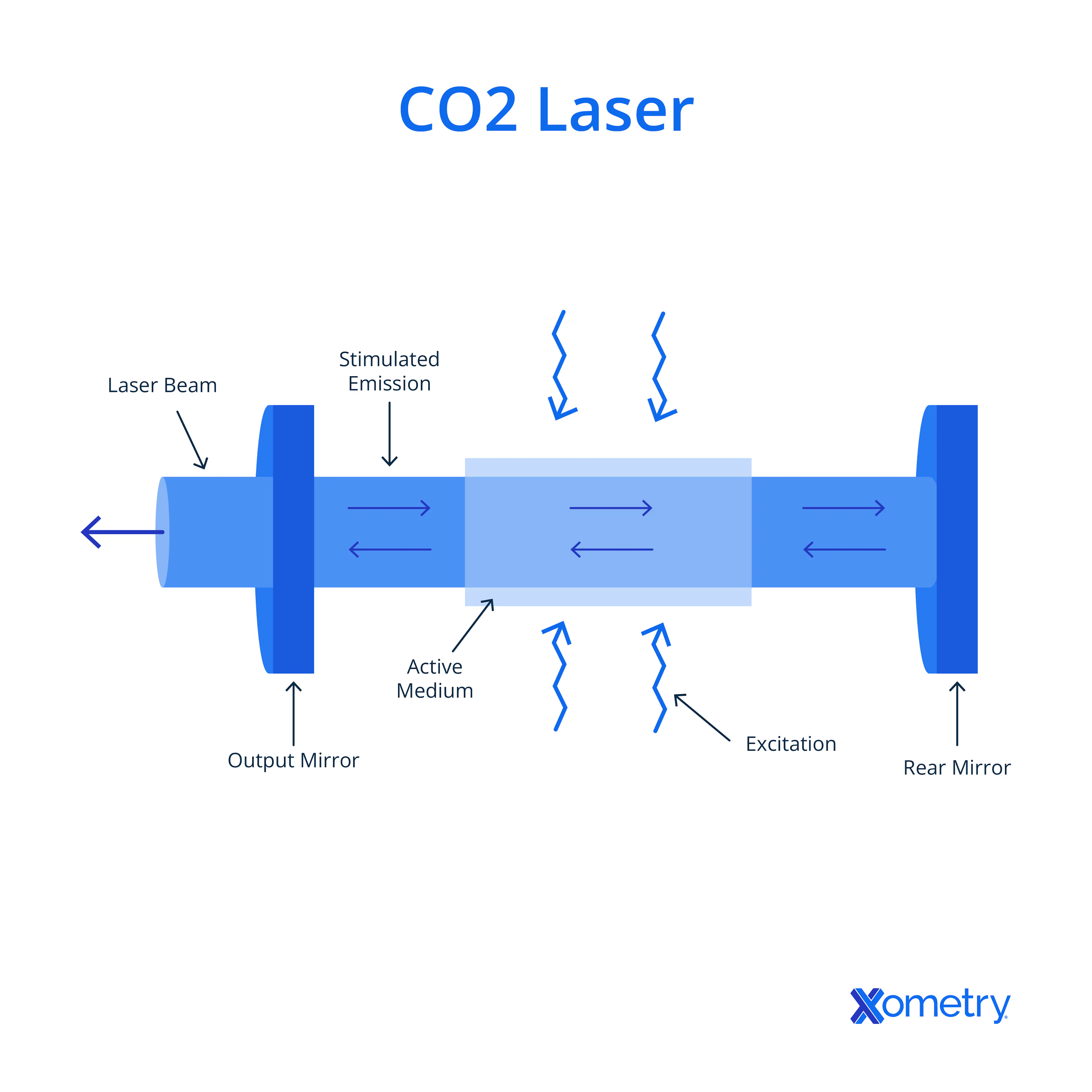
- CO2 Lasers: CO2 lasers range in power from a few hundred mW to 12 kW. The stimulated emission device is the gas itself. There are two types: low-cost DC (or glass tube) devices and RF devices. Low-cost DC (or glass tube) devices have a short life and lower precision, decrease in power output as they age, and are disposable. RF (“metal” or “ceramic” devices) are much higher cost, have tighter beams and longer life, and are fully refurbishable. For both types, the emission frequency is 10.6 μm.
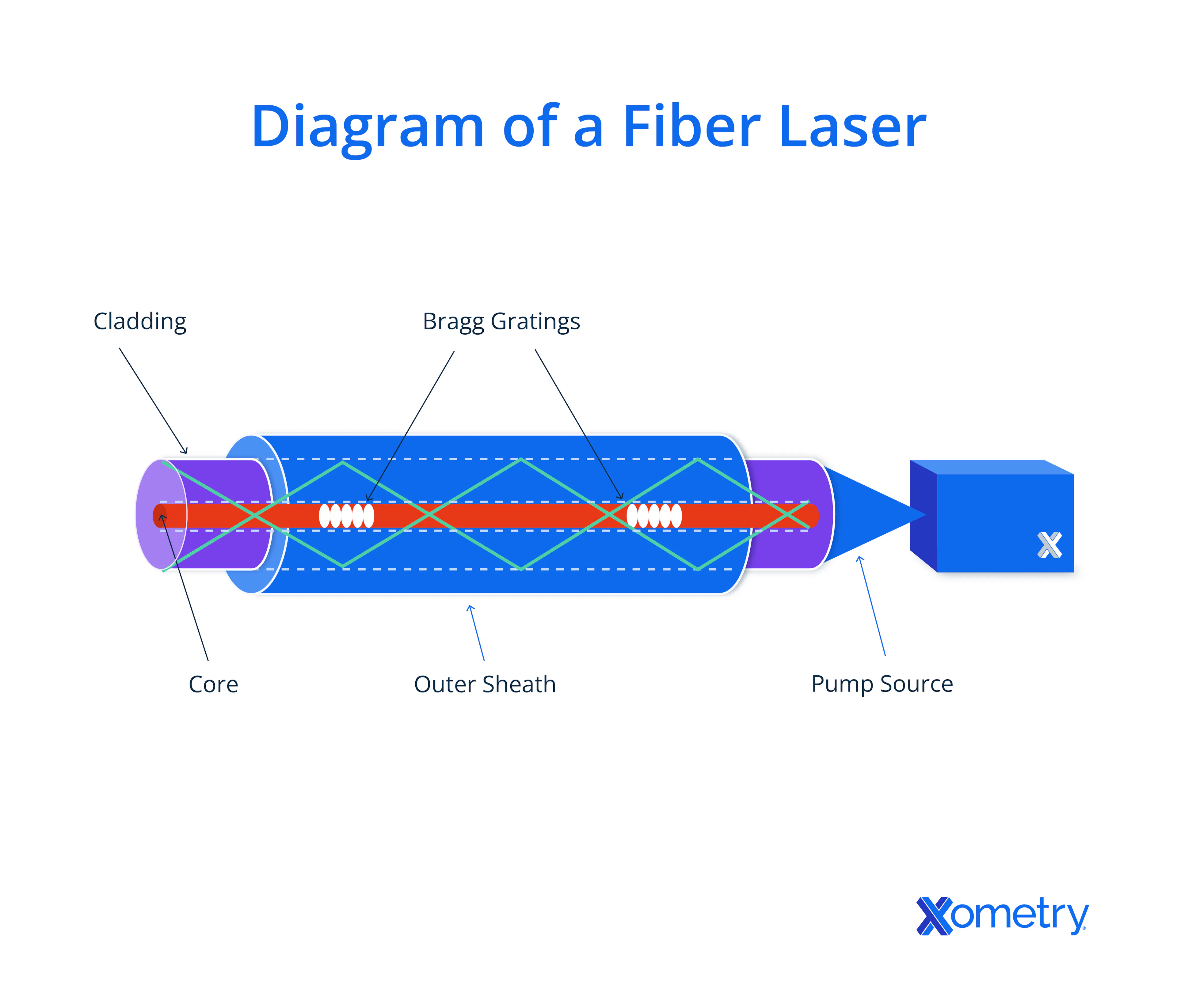
- Fiber Lasers: Fiber lasers use silica glass rods, doped with various chemistries, as the stimulated emission device, in much the same way as the ruby rod of a ruby laser works. The dopants define the emission frequency of the device. In the case of fiber (or solid-state) laser devices for laser cutting, these dopants are generally Neodymium—Yttrium—Aluminum—garnet (NdYAG), emitting infrared radiation at 1064 nm.
Invention of the Maser (1953)
The MASER (Microwave Amplification by Stimulated Emission of Radiation) is the microwave equivalent of a laser. It has coherent microwaves rather than light and is also generated in a stimulated emission device—commonly a ruby rod held at cryogenic temperatures; hydrogen cyanide; or ammonia gas. The first MASER was demonstrated by Charles Townes, at Columbia University in 1953. These devices are now widely used including: as microwave amplifiers in radio telescopes and radar technology, in microwave signal reception equipment in which low noise is critical, and in tight beam transmission systems—both as signal amplifiers and as coherent emission devices.

Invention of the Laser (1960)
The first practical demonstration of the previously theorized stimulated emission device producing laser light was by Theodore Maiman at Hughes Research Laboratories in 1960. His technology quickly found application as a range-finder device in military equipment, though it is now widespread across a wide spectrum of applications.
Invention of Fiber Optic Laser Cutting (1963)
The first fiber optic laser device was developed by Elias Snitzer at the American Optical Company in Massachusetts in 1963. Its first commercialization as an industrial tool was in 2007 in a new class of fiber laser cutting machines by Salvagnini SA in Italy, and in other thermal cutting techniques.
Invention of CO2 Laser Cutting (1963)
The CO2 laser (carbon dioxide laser) was first developed by Kumar Patel at AT&T Bell Labs. Being lower cost and higher efficiency than a synthetic ruby laser, the device quickly found applications in industry, particularly in the assisted gas laser cutting machines from Western Electric Corp. in the early ’70s.
Invention of Crystal Laser Cutting (1964)
The crystal laser is a solid-state device (more precisely, a liquid crystal laser), which uses a liquid crystal laser process. This device allows tuning of both wavelength and polarization within the stimulated emission device by adding dopants into the liquid crystal. The first practical demonstration was reported by a research group in the Soviet Union, Il’Chishin in 1980. These devices have found diverse applications in environmental sensing, biomedical sensing, and in surgical cutting/cauterization procedures.
Direct Diode Laser Devices (1962)
There is an expectation that solid-state and CO2 lasers will begin to phase out of widespread use as direct diode laser (DDL) devices increase in power. Postulated by von Neumann in 1953, the first gallium-arsenide-based laser diodes were demonstrated in 1962 by Bob Hall at the General Electric Research Center and coincidentally by Marshall Nathan from IBM’s T.J. Watson Research Center. Semiconductor laser devices are just starting to revolutionize the laser machining industry.
Water Guided Laser Cutting
Some machines now include water assistance in the cut. Here, the laser energy is “injected” into a water stream to aid cooling and slag clearance and to improve precision and beam control. The water tends to be continuous and the laser is pulsed for best cooling and optimal cutting.
5-Axis Laser Cutting
5-axis laser machining allows angled holes without extra setups, consistent chamfer cuts around complex shapes, and more rapid processing of highly complex parts.
The Future of Laser Cutting Technology
The range of proposed and currently researched areas of advancement in laser machining is extensive and varied. Listed below are the advanced or theoretical innovations in laser cutting:
- Beam-shaping approaches are developing, improving cut efficiencies in the gasless cutting of thin materials.
- Researchers are pursuing the use of masks combined with excimer laser devices. These devices will cut or engrave microstructures in a single exposure, moving the precision of reproduction from the movement of the laser or workpiece to a mask that can be slow cut with the highest precision. The use of masks will facilitate fast reproduction on simpler machines.
- Huge improvement in the speed of manufacture of silica glass optical components is being researched by use of staged laser ablation techniques. If successful, this innovation will produce a surface quality that requires only the final, light polishing stage.
- Rapid manufacture of nitinol surgical implants is increasingly possible using custom laser machining equipment. This innovation aims to allow microstructures to be directly manufactured in a single-stage process.
- Manufacture of multiple cascaded diffractive optical elements (DOEs) is becoming possible by the use of neural network training algorithms for beam shaping. Multiple layered diffraction patterns create complex and precise beam shaping for single-exposure ablation of massively complex, finely detailed patterns.
Summary
This article presented the history of laser cutting, explained what it is, and discussed the different milestones in the history timeline. To learn more about laser cutting, contact a Xometry representative.
Xometry provides a wide range of manufacturing capabilities, including sheet cutting and other value-added services for all of your prototyping and production needs. Visit our website to learn more or to request a free, no-obligation quote.
Disclaimer
The content appearing on this webpage is for informational purposes only. Xometry makes no representation or warranty of any kind, be it expressed or implied, as to the accuracy, completeness, or validity of the information. Any performance parameters, geometric tolerances, specific design features, quality and types of materials, or processes should not be inferred to represent what will be delivered by third-party suppliers or manufacturers through Xometry’s network. Buyers seeking quotes for parts are responsible for defining the specific requirements for those parts. Please refer to our terms and conditions for more information.