Top Tube Bending Design Tips

Our top tips for optimizing and improving your bent tube designs.


Xometry offers a full suite of custom tube bending services for your application. Whether you are looking for standard rotary draw tube bending or precision mandrel tube bending, Xometry offers different processes to meet your requirements for tube bending and tube fabrication services in both low and high volumes. Xometry also offers laser tube cutting services for parts that include cut features such as holes, slots, and more.
Modern tube bending techniques make it possible to form more complex shapes from tube stock. That said, designers should strive to optimize for manufacturability. An optimal design will cost less and be able to be produced more rapidly. This article will cover the top design guidelines and tips to help you achieve a highly manufacturable design for tube bending processes. The topics we will cover include:
- Material Choice
- Bend Radii
- Bend Variations and Quantities
- Distance Between Bends
- Tube Sizes
- Bend Shapes


Material Options and Considerations
Xometry offers various materials for tube bending, such as aluminum, steel, stainless steel, and brass, to name a few. Some materials bend with less difficulty than others. The easier it is to bend, the more likely your design will be successfully manufactured without defects. When picking a suitable material for your project, you should strive to balance your required material characteristics with the bendability of the material. A material’s ability to be bent is by its elongation limit percentage. You can calculate a tube’s theoretical minimum elongation required given its outer diameter and the bend’s centerline radius using the following formula:
Elongation Required = [(Ø/2)/CLR] x 100
Pro Tip: Pick materials with high elongation limits, like steel, when possible to aid manufacturability and reduce the likelihood of defects. Use larger bend radii for materials with lower elongation limits.
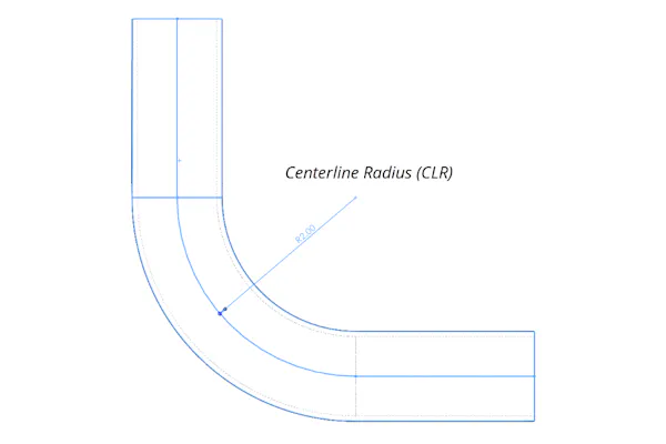
Diagram of the centerline radius of a bend.
Bend Radii
The bend radius of a tube is from the radius to the centerline of the tube. This curve is commonly referred to as the centerline radius and abbreviates as “CLR.” The minimum achievable bend radius will depend on factors such as the type of material and its wall thickness. Keep CLR at least 2*Ø and below 6” radius when possible. Your radius should be twice the size of the outer diameter of the tube. For example, if you use tubing with a 1” outside diameter, you should design your bends with at least a 2” CLR. This CLR is ideal because tooling to produce a “2*Ø” radius is common, and most materials won’t have an issue with this bend size. Designing below this may incur charges for specialized tooling and increase risk. For large bends which require the roll bending method, we recommend following the 7*Ø guideline. See a list of Xometry's standard tube sizes here.
Pro Tip: Limiting your centerline radius to below 6” and designing bends in whole number multiples of the OD (e.g., 1*Ø, 2*Ø, 3*Ø, etc.) will help avoid custom tooling charges and longer lead times. 2*Ø tooling is the minimum recommendation for draw bending and the most common tooling size.
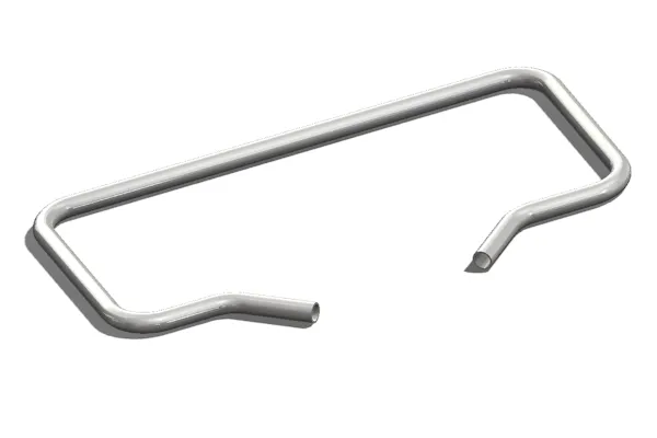
A bent tube part containing multiple bends.
Bend Variation and Bend Quantity
Different sizes of bends require different tools to produce those bends. With this in mind, it’s best practice to stick to one bend size across all bends to reduce tooling complexity and decrease cost. Using more than one size of bend radii will necessitate multiple setups or the use of a machine with multi-stack tooling. As a part with different sized bends is produced, fabricators must move it from one die set to another, which decreases production efficiency. Designers should also be mindful of the number of bends on a single part. Manufacturing complexity increases as the number of bends increases. Parts with many bends can run into issues where specialized machines or tooling are required to prevent the piece from interfering with and fouling the equipment during the bending process.
Pro Tip: Try to limit or avoid bend variations altogether to keep cost and lead times lower. Consider possible interference issues when designing parts with multiple bends.
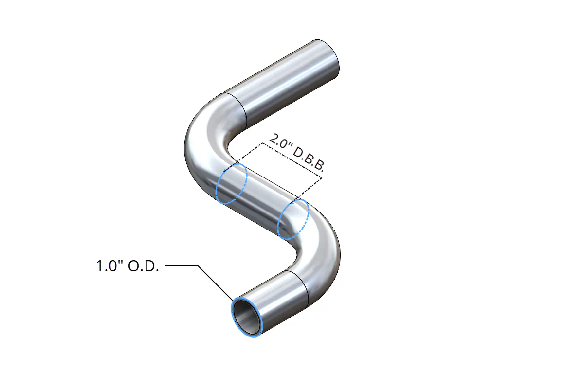
Diagram demonstrating bend distance between two bends on a part.
Distance Between Bends
The distance between bends, or “DBB” for short, is an essential consideration in multi-bend designs. DBB is the length that remains straight before the first or next bend. Having enough straight distance is crucial to allow the tooling to grip the part during bending. Having too short of a gripping area reduces leverage which leads to slippage and requires the machine to exert greater forces to produce the next bend, which can wear down machinery and tooling more quickly. Multi-stack machines and compound tooling can work around a short DBB, but these setups will come at a higher cost.
Pro Tip: Maintain a minimum straight distance of at least 2xØ between bends; the more space, the better.


Tube Sizes
Choosing standard-sized tubing is vital regarding low costs and lead times. Common tubing materials will generally be more readily available and be suitable for orders of virtually any size. If a non-standard size is specified, it will require a custom material order or even a custom extrusion--drastically increasing lead time, pricing, and minimum batch requirements. Using standardized tubing also means the manufacturer is more likely to have tooling for that size of tubing, which helps avoid costly custom tooling charges.
It is essential to recognize the difference between pipe and tube stock because their measurements differ. For example, a 2” round tube will measure 2” outer diameter, whereas a 2” nominal pipe, schedule 40, will have an outer diameter of 2.38”. Pipes are for pressurized applications with their measurements described by inner nominal diameter plus the wall thickness, called schedule. Piping is always round, where tubes can be various shapes from round, rectangular, hexagonal, etc. A tube is for general purpose applications, including structural components and their measurements described by its outer and inner diameters. Tube also has tighter tolerances on dimensions.
Pro Tip: Design around readily available standardized tube sizes. Refer to Xometry’s Standard Tube Sizes page for a list of commonly stocked pipe and tube materials!
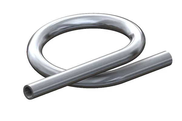
A tube that has been bent over itself.
Tube Bending Shapes to Avoid
Certain bent shapes are highly complex or impossible to produce by bending from one piece. Some complex bends require sectioning and welding, which greatly affect cost and efficiency. The reason is that as a tube is bent too far, it can bend back towards the machinery and foul it. Below are some guidelines on shapes to avoid in your bent tube designs:
- “Knot-like" bends
- Tight coils
- Bends greater than 180 degrees
- “q" shapes
Pro Tip: Try to keep bends under 180 degrees and avoid designs where the tube crosses over itself.
