Understanding and Preventing Vapor Smoothing Defects


8 tips to prevent vapor smoothing defects in your parts


Xometry's vapor smoothing service is an excellent way to improve the look and feel of your custom-ordered 3D printed parts. Utilizing automatic vapor smoothing technology, we are able to achieve consistent and repeatable results with ease. While there are many benefits of chemical vapor smoothing, including smoothing layer lines, sealing micro gaps, and enhancing mechanical performance, the process can introduce defects if your part designs aren't done correctly.
In this guide, we will familiarize you with the most commonly seen vapor smoothing defects, as well as provide tips on how to prevent them from occurring in your parts. Before we jump into the different types of defects you can expect to come across with vapor smoothing, let's first quickly recap what the process is and how it works.
What is Vapor Smoothing?
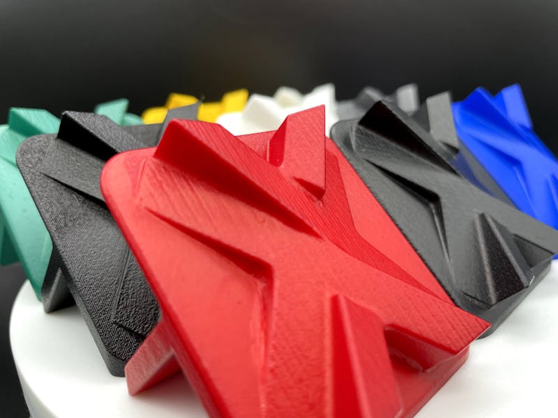
An array of SLS 3D printed vapor smoothed parts dyed in various colors
Unlike physical smoothing processes such as sanding or media tumbling, vapor smoothing does not remove material on the workpiece. Instead, a vapor finishing agent is introduced into a sealed processing chamber with the parts. Parts are racked, or hung, in the chamber to maximize the surface exposure to the vapor. The vapor clings to the part surface where it causes a controlled chemical melt. This reduces the surface peaks and valleys by liquifying and redistributing material and evening the surface. The melt also has the effect of enhancing shine.
Once the parts are finished, the chamber is heated to evacuate the finishing agent to a collection vat. No residue is left on the parts. Smoothed parts are then ready for shipping or another secondary process such as dyeing.
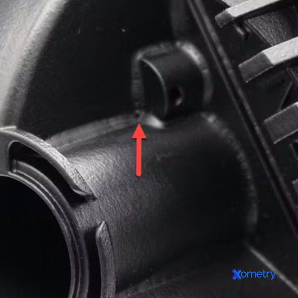
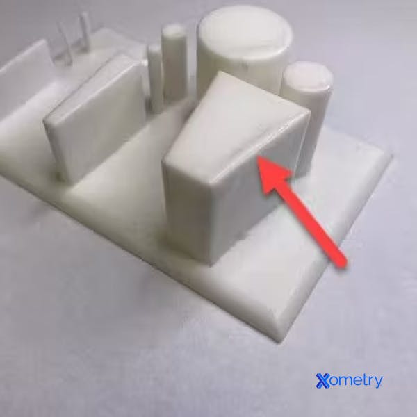
Close up photo of bridging defect on a vapor smoothed part
Bridging
The surface of a part may bubble during the liquefaction stage of the vapor smoothing process. The bubbling surface may cause the material to form a thin shell that connects between features like small gaps or walls of sharp corners. In some cases, a razor can be used on the bridging shells to free up the affected elements.
Design Tip:
Bridging can be mitigated by increasing the distance between gaps and adding ample radii to sharp internal corners.
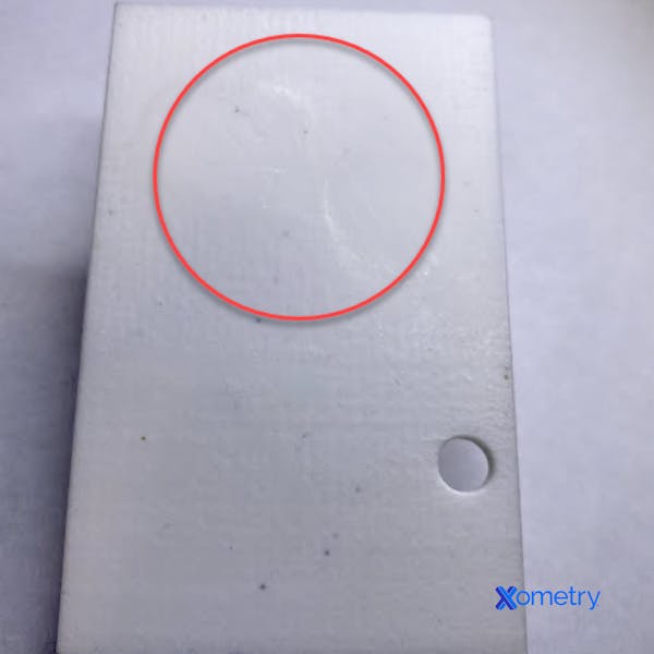
Blister on a flat surface of a vapor smoothed part
Bubbles / Blistering
Similar to bridging, blistering results from the surface bubbling during the liquefaction stage. Sometimes larger bubbles can form and remain in place while the solvent evacuation process is underway. After this, the bubble may harden and leave a blister-like appearance. Typically these are found on broad flat surfaces and sharp internal crevices.
Design Tip:
Avoid broad flat surfaces; organically shaped surfaces are less likely to blister. Adding radii on internal corners will also help mitigate bubbling and other defects.
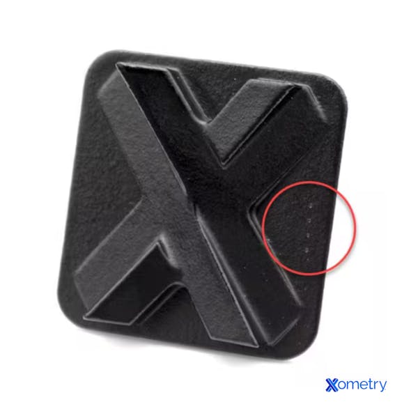
Close up of racking "bite marks" on a vapor smoothed part
Bite Marks
The parts must be suspended during the vapor smoothing process to achieve a uniformly applied finish. Racking is performed using hooks or clips to suspend the pieces in open air. Hooks are the preferred racking method as they will leave minimal impressions on the inside of the racked hole. "Bite marks" are a defect associated with the impression left from clips used to hold parts that do not have features that allow for hooking. These marks are usually more noticeable on softer materials like TPU.
Design Tip:
Adding a hole or feature that can be used to hook through and rack the part instead of clamping will prevent bite marks from appearing on cosmetically important faces. If you can't modify your design to add racking features, be sure to note which faces or features of your part are cosmetically important, and our technicians will do their best to avoid clipping onto those areas. While building your quote, you can specify notes within the Xometry Instant Quoting Engine notes section or upload a drawing containing the respective notes.
Edge pooling on a sharp edge of a vapor smoothed part
Edge Pooling
Abrupt turns on flat parts' sides may result in a visible bump around the edge. Bumps are caused by the liquified material moving with gravity to the edge and solidifying in place. Edge rounding and pooling can affect feature tolerances.
Design Tip:
Radii on sharp edges of flat-sided features will help mitigate the pooling of the liquified material.
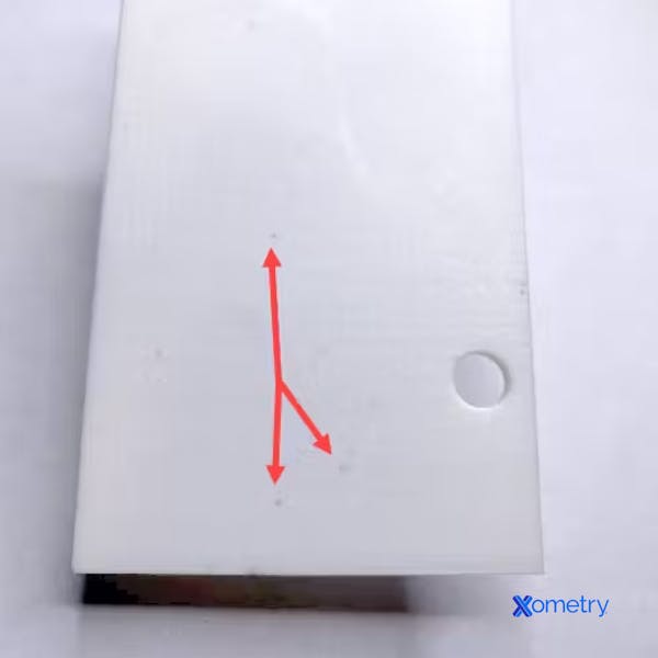
Example of speckling on a white part
Speckling
Tiny dots of dark stain can appear on the surface of lightly colored materials after going through the process. We refer to this as speckling. Speckles are typically more noticeable on natural finishes and on surfaces dyed lighter colors such as yellow or red.
Design Tip:
Dying or selecting materials of darker colors, such as black, green, or blue, will reduce the visibility of speckling.
Holes
Unintentional holes may appear on very thin areas. This happens when the surface on each side of the thin wall has liquified to the point that the center has become fully liquid. This causes a hole to form when the material flows and re-hardens.
Design Tip:
Ensure the thickness of walls maintains a thickness of at least 1mm to prevent the formation of holes. This minimum wall thickness is recommended for most additive processes in general and will help avoid other issues.
Incomplete Features
During vapor smoothing, cantilevered or long thin protrusions may be shortened or form incompletely. This happens because the tips will liquefy, move, and re-solidify once the solvent evaporates.
Design Tip:
Avoid designing features that go below 1mm in wall thickness, such as sharp points or knife edges.
Conclusion
Following these tips can allow you to harness the power of vapor smoothing to enhance a part's performance and finish. Many flaws can be avoided by keeping certain design principles in mind, such as maintaining minimal feature size and adding appropriate radii. For more resources on 3D printing, check out our Ultimate Guide to 3D Printing and our design guides.