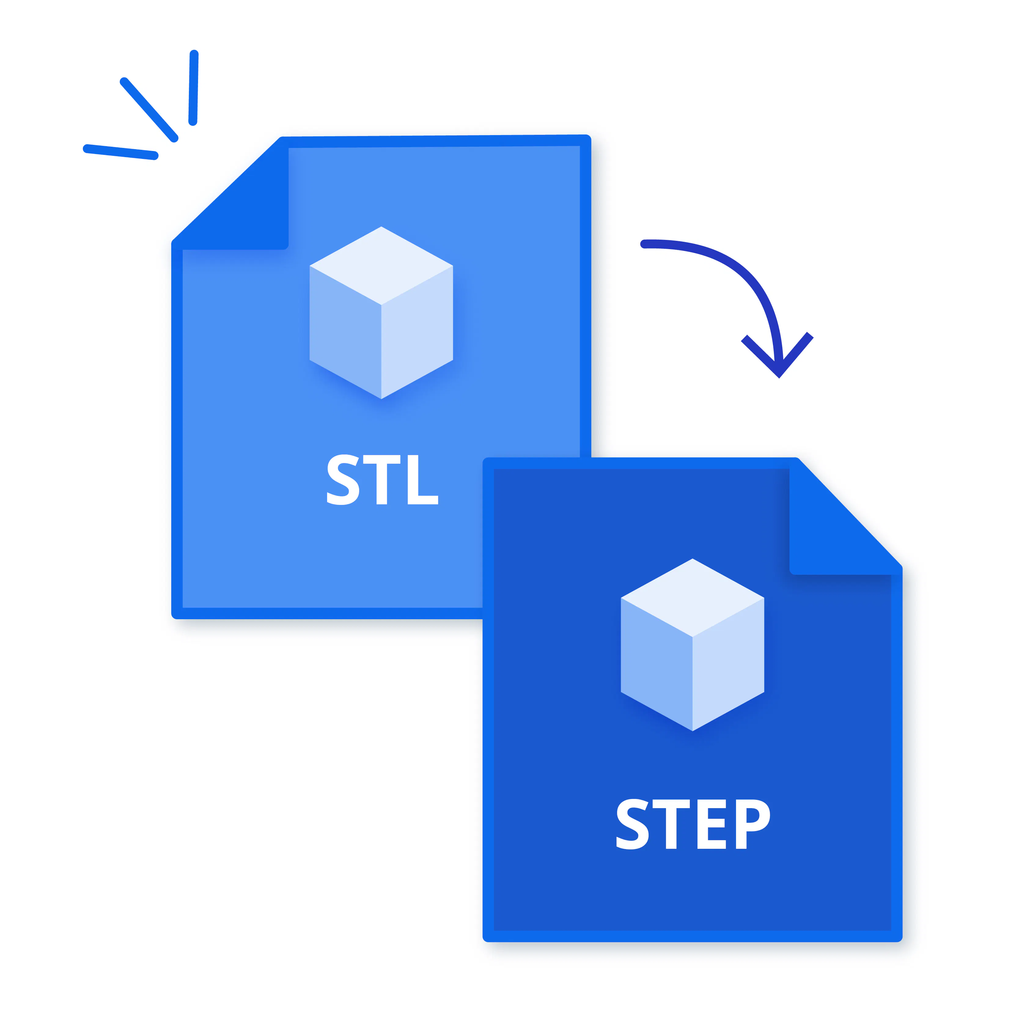
STL File to STEP Converter: How to Convert STL File to STEP File


Converting a Standard Triangle Language (STL) file to the Standard for the Exchange of Product (STEP) format transforms a mesh‑based model into a solid, feature‑based representation suitable for engineering workflows. The process begins with importing the STL mesh into conversion software that reconstructs surfaces and generates a watertight solid body. A STEP file enables machining and mold design but does not inherently support parametric editing unless the geometry is rebuilt manually or using advanced recognition tools. The conversion delivers practical benefits, improved compatibility with Computer-Aided Design (CAD) software, smoother integration into tooling design, and greater control over dimensional adjustments for casting or prototyping projects.
How to Convert STL File to STEP File?
To convert a Standard Triangle Language (STL) File to a Standard for the Exchange of Product (STEP) file, follow the six steps below.
- Get a conversion tool. A dedicated conversion tool provides the functions needed to interpret mesh data and rebuild it as a solid model. The software establishes a workflow that supports accurate translation from triangulated geometry to a Computer-Aided Design (CAD)‑ready format.
- Upload your STL file. Importing the STL file loads the mesh into the workspace, so the software analyzes its structure. A successful upload ensures that every triangle becomes available for repair and reconstruction.
- Repair the mesh. Mesh repair corrects gaps, flipped normals, and irregular facets that interfere with solid creation. A clean mesh strengthens the accuracy of the shape generated during the next stage.
- Transform the mesh into a shape. Converting the mesh into a shape replaces raw triangles with mathematically defined surfaces. The transformation creates a structured model that supports further refinement.
- Transform your shape into a solid. Solid conversion seals the surfaces into a closed volume recognized by CAD systems. A watertight solid supports machining, mold design, and dimensional adjustments.
- Export your solid formation into a STEP file. Exporting to STEP produces a neutral CAD format that integrates smoothly with engineering and manufacturing software. The STEP file preserves the solid body so it functions reliably in downstream design and production workflows.
NOTE: STL file data does not contain information on curves. Any curve, radius, circle, etc., will comprise a series of lines and planes. An STL to STP conversion does not guarantee the part can be produced in a process like CNC without additional CAD work or the need to reproduce the part in a solid CAD modeling program.
Why Should You Convert an STL File to a STEP File?
You should convert a Standard Triangle Language (STL) file to a Standard for the Exchange of Product (STEP) file because it creates a solid, feature‑based model that supports precise engineering work and structured Computer-Aided Design (CAD) development. A STEP file strengthens accuracy because the format preserves surfaces, edges, and volumes in a way that aligns with manufacturing requirements. The conversion improves interoperability by allowing the model to function across a wide range of design software, which supports machining, mold creation, simulation, and dimensional refinement. The process delivers practical value by transforming a mesh‑based structure into a fully defined solid that integrates smoothly into professional engineering workflows.
What is an STL File?
A Standard Triangle Language (STL) file represents a 3-dimensional (3D) model through a collection of triangular facets that describe the outer surface of a part without storing parametric features or material properties. The format supports additive manufacturing because the triangulated structure provides a clear boundary for slicing and layer‑based production. The structure of an STL file limits interoperability in Computer-Aided Design (CAD) environments since the mesh lacks editable features, dimensional constraints, and design history required for advanced engineering work.


What is a STEP File?
A Standard for the Exchange of Product (STEP) file represents a standardized Computer-Aided Design (CAD) format that stores a 3-dimensional (3D) model as a fully defined solid with surfaces, edges, and volumes preserved in a neutral structure. The format supports engineering and 3D modeling workflows because its parametric nature maintains precise geometry suitable for machining, mold development, and technical documentation. A STEP file strengthens accuracy in assemblies by preserving relationships between components, allowing complex structures to maintain alignment, fit, and dimensional integrity across different design software.
Which Programs Can Convert STL to STEP?
The programs that can convert Standard Triangle Language (STL) to Standard for the Exchange of Product (STEP) are listed below.
- SolidWorks: A professional Computer-Aided Design (CAD) platform that converts STL meshes into editable STEP solids with high accuracy. It supports complex assemblies and preserves geometry details for manufacturing-ready files.
- Fusion 360: Cloud-enabled CAD tool that imports STL and outputs STEP files efficiently. Offers mesh-to-solid conversion along with integrated modeling, making it suitable for both design and production workflows.
- FreeCAD: Open-source CAD software capable of transforming STL meshes into STEP solids. Provides mesh cleanup and precise control over the conversion process, ideal for preparing parts for machining or 3D printing.
- AutoCAD: AutoCAD can import STL and support limited mesh editing, but does not natively support robust mesh-to-solid or STEP export without plugins or the use of other Autodesk tools (Inventor or Fusion 360). Supports multiple CAD formats, ensuring compatibility with various manufacturing and engineering platforms.
- AnyConv (Online Converter): Browser-based tool for quick STL-to-STEP conversion without installation. Best for small to medium files and fast format changes, with a straightforward workflow for sharing or manufacturing preparation.
- MeshConvert (Online Converter): Offers multi-format support (STL and STEP). Maintains fundamental mesh integrity during conversion and is helpful for users who need simple online solutions.
"Converting STL to STEP is best approached as a salvage and reconstruction exercise rather than a true conversion. An STL arrives stripped of design intent so the real work is judging whether the mesh is good enough to justify rebuilding it into a solid. Clean, low-noise meshes with reasonable triangle density can usually be surfaced and closed into a usable STEP solid for machining, fixturing, or mold references, but dense scans and hobby-grade meshes often demand more time repairing artifacts than redesigning the part outright. The moment surface fitting begins, accuracy becomes a tolerance decision rather than a guarantee, and every downstream edit reflects that compromise. In practice, STL-to-STEP is most valuable when recovering legacy parts, vendor geometry, or scan data where no native CAD exists; when full parametric control is required, rebuilding the model from measurements remains faster, cleaner, and more reliable than forcing intelligence back into a faceted file."
Why Use Fusion 360 or SolidWorks for STL to STEP Conversion?
Using Fusion 360 and SolidWorks for Standard Triangle Language (STL) to Standard for the Exchange of Product (STEP) conversion provides strong advantages because each software delivers high accuracy during surface reconstruction and solid creation. These tools can process triangulated geometry, but they do not modify triangle quality inherently—input quality remains a limiting factor. Each system offers refined control over geometry, allowing detailed adjustments that preserve dimensional integrity throughout the conversion process. Professional workflows benefit from the software because their environments support machining preparation, assembly development, simulation tasks, and reliable integration with manufacturing‑ready Computer-Aided Design (CAD) formats.
When should CAD Programs Be Preferred Over Online Tools?
Computer-Aided Design (CAD) programs should be preferred over online tools when a project requires precise control over complex geometry, detailed assemblies, and engineering‑grade accuracy. A CAD environment supports solid modeling, constraint management, and dimensional refinement, which strengthens reliability during machining, mold development, and production planning. High‑value manufacturing tasks benefit from the CAD workflows because the software maintains structural integrity, preserves relationships between components, and delivers consistent results across advanced design operations.
Can All CAD Programs Convert STL to STEP?
No, not all Computer-Aided Design (CAD) programs can convert Standard Triangle Language (STL) to Standard for the Exchange of Product (STEP) conversion because the process requires tools capable of rebuilding a mesh into a solid model. Programs without mesh‑repair functions, surface reconstruction features, or solid‑generation capabilities lack the structure needed to translate a faceted file into a parametric format. CAD software designed for drafting or basic visualization does not provide the geometric control required for accurate STEP creation, which limits its usefulness in engineering and manufacturing workflows.
What are the Best STL to STEP File Converters?
The best Standard Triangle Language (STL) to Standard for the Exchange of Product (STEP) file converters are listed below.
- AnyConv: A fast online converter that handles STL to STEP quickly with minimal setup. Ideal for users who need quick file format changes without installing software.
- MeshConvert: There is no prominent or verifiable tool widely known as "MeshConvert" that reliably converts STL to STEP with mesh-to-solid capabilities.
- FreeCAD: A desktop Computer-Aided Design (CAD) program that imports STL meshes and converts them into editable STEP solids. Provides control over geometry cleanup and accuracy, suitable for manufacturing or detailed editing.
- CAD Exchanger: Offers both online and desktop options with high compatibility for different CAD formats. Maintains better geometry integrity during conversion, making it suitable for professional workflows.
- eMachineShop Online CAD Converter: Browser-based tool for converting STL, STEP, IGES, and other formats. Simple interface and moderate speed make it useful for rapid format preparation.
- Blender (with add-ons): Converts STL meshes into STEP-compatible files after mesh-to-solid processing. Best for users familiar with mesh editing who need intermediate control over complex models.
Why Use Xometry to Convert STL Files to STEP Files?
Use Xometry to convert Standard Triangle Language (STL) to Standard for the Exchange of Product (STEP) files because it provides a structured environment with strong attention to accuracy, geometric stability, and manufacturing readiness. Blender does not natively support STEP file export; third-party add-ons or external tools are required, and results are not engineering-grade. Clean geometry, dependable file translation, and extensive CAD support ensure consistent outcomes with complex models Xometry, but it does not itself generate solids from mesh files.
How to Use a CAD Program to Convert STL to STEP
To use a Computer-Aided Design (CAD) program to convert Standard Triangle Language (STL) to Standard for the Exchange of Product (STEP), follow the four steps below.
- Open the STL file in the CAD program. Open the STL file to load the mesh into the modeling workspace, where every triangle becomes accessible for inspection. The imported mesh establishes the foundation for reconstruction, repair, and solid‑body creation.
- Convert the mesh into a solid model. Convert the mesh into a solid to replace faceted geometry with continuous surfaces that support engineering accuracy. The solid formation process strengthens dimensional stability and prepares the model for parametric use.
- Export the finished model as a STEP file. Export the solid as a STEP file to generate a neutral format that preserves surfaces, edges, and volumes for manufacturing workflows. The exported file supports broad compatibility across design, machining, and simulation environments.
- Adjust settings to increase precision. Adjust precision settings to refine surface quality, triangle interpretation, and tolerance control during conversion. Higher accuracy settings maintain geometric fidelity and support reliable performance in downstream engineering tasks.
How to Check Accuracy after Converting STL to STEP Files?
To check accuracy after converting Standard Triangle Language (STL) to Standard for the Exchange of Product (STEP), follow the four steps below.
- Compare the converted solid with the original mesh. Compare the solid model with the original STL mesh to confirm that every major contour and surface aligns with the intended geometry. The comparison verifies that the conversion preserved dimensional stability without introducing distortion.
- Inspect surface continuity across the model. Inspect surface transitions to confirm that every region forms a smooth and uninterrupted boundary. Continuous surfaces indicate that the reconstruction process created a stable foundation for engineering work.
- Measure key dimensions within the Computer-Aided Design (CAD) environment. Measure critical dimensions to confirm that the STEP file reflects accurate lengths, widths, and heights derived from the original mesh. Dimensional checks validate that the conversion maintained proportional integrity.
- Evaluate the solid for gaps, overlaps, or unintended voids. Evaluate the model for structural defects that interfere with machining, simulation, or assembly preparation. A defect‑free solid demonstrates that the conversion produced a reliable and manufacturable geometry.
Is It Possible to Convert STEP to STL?
Yes, it is possible to convert a Standard for the Exchange of Product (STEP) file because a solid model stored in a STEP format has comprehensive surface and volume data that supports triangulation. The process to convert STEP to STL generates a mesh-based representation suitable for additive manufacturing, rapid prototyping, and digital visualization, allowing the solid geometry to act as a faceted model in production workflows.
How to Use an Online STL to STEP Converter?
To use an online Standard Triangle Language (STL) to Standard for the Exchange of Product (STEP) converter, follow the five steps below.
- Upload the STL file to the converter. Upload the STL file through the converter interface to place the mesh model into the processing system. The uploaded file establishes the starting geometry for surface reconstruction and solid creation.
- Select STEP as the output format. Choose STEP as the target format, so the converter prepares a neutral Computer-Aided Design (CAD) file instead of a mesh‑based result. The selected format supports downstream engineering tasks, including modeling, machining preparation, and assembly development.
- Adjust conversion settings for quality and tolerance. Set quality and tolerance values to control how closely the STEP geometry follows the original STL mesh. Tighter tolerances protect critical dimensions and reduce the risk of unwanted shape deviations.
- Start the conversion and generate the STEP file. Initiate the conversion, so the service processes the mesh, reconstructs surfaces, and builds a solid model in STEP format. The generated file becomes ready for import into CAD workflows that require precise and editable geometry.
- Download and verify the converted STEP model. Download the finished STEP file and load it into a CAD environment to review geometry, dimensions, and surface continuity. The verification step confirms that the online conversion produced a stable, accurate model suitable for engineering and manufacturing use.
Where can you Find STL to STEP Converter Online?
You can find the Standard Triangle Language (STL) to Standard for the Exchange of Product (STEP) converter online through the tools listed below.
- AnyConv: Use AnyConv to convert STL files into STEP format through a straightforward browser‑based interface that processes files without installation. The software supports neutral CAD outputs that maintain stable geometry for engineering tasks.
- FreeCAD: Use a desktop application of FreeCAD utilities to convert STL files through open‑source algorithms that reconstruct surfaces and create solid bodies.
- Online CAD Translation Services: Use online CAD translation software that specializes in converting mesh files into solid STEP models through automated reconstruction methods. The services support strong compatibility with engineering workflows that require precise and editable geometry.
Is It Safe to Use an Online STL to STEP Converter?
Yes, it is safe to use an online Standard Triangle Language (STL) to Standard for the Exchange of Product (STEP) converter. Using an online STL to STEP converter remains safe when the service maintains secure file handling, encrypted transfers, and clear data‑protection practices. A trusted software protects uploaded models from unauthorized access, which supports confidence during engineering, prototyping, and manufacturing preparation.
How long does It Take to Convert an STL File to STEP?
The time to convert a Standard Triangle Language (STL) to a Standard for the Exchange of Product (STEP) file is from 10 seconds to more than an hour, but it varies with smaller and simpler models completing the process faster than large or intricate meshes. A detailed mesh increases processing demands because every triangle requires interpretation during surface reconstruction. Software performance influences speed, since stronger algorithms handle dense geometry with greater efficiency. Computer hardware contributes to the final duration because higher processing power and greater memory capacity reduce delays during solid formation and export.
What Problems Can Occur When Converting STL to STEP?
The problems that can occur when converting Standard Triangle Language (STL) to a Standard for the Exchange of Product (STEP) are listed below.
- Mesh Errors: Mesh errors create broken triangles or disconnected regions that interfere with surface reconstruction during conversion. A flawed mesh structure produces unstable solids that reduce reliability in engineering workflows.
- Loss of Detail: Loss of detail occurs when fine geometric features fail to transfer from a faceted mesh into a solid model. A simplified surface reduces accuracy and affects precision during manufacturing preparation.
- Scaling Issues: Scaling issues arise when unit settings differ between the STL file and the STEP export environment. A mismatch in units alters dimensions and disrupts alignment in downstream modeling tasks.
- Unsupported Features: Unsupported features appear when the STL mesh contains shapes that do not translate into parametric surfaces. A complex or irregular region forces the converter to approximate geometry, which reduces fidelity.
- Corrupted Files: Corrupted files interrupt the conversion process by preventing the software from reading the mesh structure. A damaged STL input produces an incomplete or unusable STEP output that fails to support engineering or production needs.
What are Common Use Cases for STL to STEP Conversion?
The common use cases for Standard Triangle Language (STL) to a Standard for the Exchange of Product (STEP) conversion are listed below.
- 3-dimensional (3D) Printing Corrections: 3D printing corrections rely on STL‑to‑STEP conversion to transform a faceted mesh into a solid model that supports precise edits. A solid format strengthens dimensional control and prepares the geometry for manufacturing adjustments.
- CAD Assembly Creation: Computer-Aided Design (CAD) assembly creation benefits from STEP files because solid models maintain defined surfaces and edges that support accurate alignment. A structured, solid format preserves relationships between components during assembly development.
- Engineering Workflow: Engineering workflow tasks depend on STEP files to maintain stable geometry that supports simulation, machining preparation, and technical documentation. A solid model strengthens reliability across every stage of the design‑to‑production process.
- Reverse Engineering: Reverse engineering processes convert STL scans into STEP solids to rebuild functional geometry from captured surfaces. A solid format supports refinement, measurement, and integration into broader design operations.
- Rapid Prototyping: Rapid prototyping uses STEP files to prepare clean, editable solids that transition smoothly from concept to production. A solid model supports accurate modifications that guide iterative development.
How to Edit an STL Before Converting to STEP
To edit Standard Triangle Language (STL) before converting to Standard for the Exchange of Product (STEP), follow the four steps below.
- Repair the mesh. Repair the mesh to correct broken triangles, holes, and disconnected regions that interfere with solid‑body reconstruction. Software (MeshLab, Blender, or FreeCAD) provides structured repair tools that restore stability before conversion.
- Remove artifacts. Remove artifacts to eliminate stray geometry, noise, or unwanted fragments that distort the final STEP model. Clean geometry supports accurate surface generation and prevents defects during solid formation.
- Scale the model correctly. Scale the model correctly to align unit settings with the intended manufacturing dimensions. Proper scaling preserves proportional accuracy and prevents dimensional errors during downstream engineering tasks.
- Merge vertices. Merge vertices to unify overlapping or duplicated points that weaken mesh integrity. A consolidated vertex structure strengthens surface continuity and prepares the model for reliable STEP conversion.
How to Convert STL to STEP Using Free Tools
To convert Standard Triangle Language (STL) to a Standard for the Exchange of Product (STEP) using free tools, follow the four steps below.
- Use FreeCAD for mesh‑to‑solid conversion. Use FreeCAD to import the STL mesh and apply surface reconstruction tools that transform faceted geometry into a solid body. The solid model produced in FreeCAD supports accurate STEP export for engineering and manufacturing tasks.
- Use Blender for mesh cleanup before export. Use Blender to refine the STL mesh by repairing defects and improving surface continuity before transferring the file to a CAD‑ready format. A cleaner mesh strengthens the reliability of the subsequent STEP conversion performed in another free tool.
- Use MeshLab for structural repair and preparation. Use MeshLab to correct holes, remove artifacts, and unify vertices to create a stable mesh suitable for solid reconstruction. A repaired mesh supports smoother processing when exported to a free Computer-Aided Design (CAD) software for STEP generation.
- Use an online STL‑to‑STEP converter for quick translation. Use a free online converter to process the STL file through automated algorithms that rebuild surfaces and generate a STEP model. The resulting file supports integration into CAD workflows that require editable and dimensionally stable solids.
"I have experience converting STL files to STEP files. The process can vary depending on the CAD software, but with the right tools, it is manageable and often useful for refining or modifying designs. That being said, staying in STEP format as long as possible with your project ensures the highest precision and compatibility before moving over to STL files for production for something like 3D printing."
Can STL Conversion Affect Model Accuracy?
Yes, Standard Triangle Language (STL) conversion can affect model accuracy because a faceted mesh transforms into a solid format through algorithms that interpret every triangle rather than preserve exact curvature. A deviation in surface reconstruction influences dimensional precision, which creates noticeable differences during engineering, machining, or prototyping tasks.
What are the Differences Between STL and STEP Formats?
The differences between Standard Triangle Language (STL) and Standard for the Exchange of Product (STEP) formats are shown in the table below.
How Xometry Can Help
3D printing is our area of expertise here at Xometry and we offer many related services, like FDM, SLS, and PolyJet. You can get a free, no-obligation quote quickly by uploading your design to our Instant Quoting page. If you need any help converting your STLs into STEP files or have any other queries, please feel free to contact one of our representatives.
Disclaimer
The content appearing on this webpage is for informational purposes only. Xometry makes no representation or warranty of any kind, be it expressed or implied, as to the accuracy, completeness, or validity of the information. Any performance parameters, geometric tolerances, specific design features, quality and types of materials, or processes should not be inferred to represent what will be delivered by third-party suppliers or manufacturers through Xometry’s network. Buyers seeking quotes for parts are responsible for defining the specific requirements for those parts. Please refer to our terms and conditions for more information.