The Xometry app works best with JavaScript enabled!
Our SolutionsIndustriesResourcesXometry EnterpriseHow Xometry WorksBecome a Supplier
Additive Manufacturing

3D Printing Service

Metal 3D Printing Service

Solutions For Every Industry
Resources3D Printing DesignWhat Is Stress-Strain Curve?
Tensile test on metal. Image Credit: Shutterstock.com/Thaweesak Thipphamon

What Is Stress-Strain Curve?

Learn more about how a stress-strain curve helps determine a material's behavior.

Xomety X
By Team Xometry
March 30, 2023
 11 min read
RECENT STORIES
Methyl Methacrylate (MMA): Definition, Uses, and Types
April 18, 2024
 12 min read

A stress-strain curve is a graphical depiction of a material’s behavior when subjected to increasing loads. Stress is defined as the ratio of force to cross-sectional area, while strain is defined as the ratio of the change in length of a dimension to the dimension’s original length. Stress-strain curves can be generated to investigate a material’s behavior when any type of load (tensile, compression, shear, bending, torsion) is applied. We will, however, will focus solely on the stress-strain curves generated by tensile loads. Stress-strain curves generated for tensile loads are important because they enable engineers to quickly determine several mechanical properties of a material including: modulus of elasticity (Young’s modulus), yield strength, ultimate strength, and ductility. A stress-strain curve is obtained by conducting a tensile test (a type of test where a load is continuously applied to a test specimen until it fractures). The stress experienced by the part is graphed on the Y-axis, while the strain is graphed on the X-axis. This article will define the stress-strain curve, its different regions, how to interpret it, and its importance to material selection.

What Is Stress?

Stress is the amount of force applied to a cross-sectional area. It’s a highly important calculation because it allows engineers to quantify the amount of force that a material can tolerate before fracturing. This parameter is used by engineers to select materials and designs that will result in safe, durable structures. The formula for stress is shown below:

Slide 1 of 1
stress formula
stress formula
stress formula

Stress formula.

Where:

  1. 𝜎 is the stress
  2. F is the applied force
  3. A is the cross-sectional area. 

The SI unit for stress is the Pascal (Pa), but pounds per square inch (psi) is also commonly used.

What Is Strain?

Strain is defined as the deformation experienced by a material relative to its original dimensions. Strain, like stress, is an essential calculation because it helps engineers quantify how much deformation a material can accommodate before it permanently deforms or fractures. The formula for strain is defined below: 

Slide 1 of 1
strain formula
strain formula
strain formula

Strain formula.

Where: 

  1. ε is the strain
  2. Lf is the final length
  3.  L0 is the initial length

Strain is a unitless value since the numbers in both the top and bottom of the formula are in units of length.

Why Is Stress-Strain Curve Important?

The stress-strain curve is important because it allows engineers to quickly determine several of the most critical and fundamental mechanical properties of any material. A single tensile test can produce a stress-strain graph, which then allows the following properties of a material to be obtained:

  1. Young’s modulus
  2. Yield strength
  3. Ultimate tensile strength
  4. Ductility
  5. Poisson’s ratio

How Is the Stress-Strain Curve Measured?

Stress-strain curves are generated automatically by modern tensile testing machines. These machines continuously monitor and record the force applied to a test specimen and the amount of deformation it experiences as a result of that load. The most commonly used test methods for tensile testing and creating standardized stress-strain curves are those issued by ASTM International. ASTM E8 standardizes tensile tests for metallic materials while ASTM D638 standardizes tensile tests for plastic materials. The steps to creating a stress-strain curve are described in the list below:

  1. Prepare the test specimen to the required dimensions.
  2. Mount the test specimen in the jaws of the tensile testing machine.
  3. Apply a continuously increasing tensile load to the specimen until it breaks.
  4. The tensile testing machine will record the stress and strain experienced by the test specimen based on readings of force applied by the load cell and displacement of the jaws holding the test piece.

What Are the Different Stress-Strains?

There are two types of stresses and strains that are described in detail below:

1. Engineering Stress and Strain

Engineering stress and strain are the stress-strain values of material calculated without accounting for the fine details of plastic deformation. These values are also referred to as nominal stress and strain. The values for engineering stress and strain are convenient for measuring the performance of a material and can be directly obtained from a standard tensile test. The formula for engineering stress is shown below:

Slide 1 of 1
engineering stress formula

Engineering stress formula.

Where A0 is the original cross-sectional area of the test specimen. The SI unit for stress is the Pascal (Pa), but pounds per square inch (psi) is also commonly used. 

The formula for engineering strain is given below:

Slide 1 of 1
engineering strain formula

Engineering strain formula.

Strain is a unitless measurement.

2. True Stress and Strain

True stress and strain are the actual stress and strain experienced by a material while taking into account its deformation during a tensile test. It is ideal for analyzing the mechanical properties of a material. True stress and strain must be calculated from experimental data related to the test specimen’s instantaneous gauge length, cross-section area, and applied load throughout the test. The formula for true stress is shown below:

Slide 1 of 1
true stress formula
true stress formula
true stress formula

True stress formula.

Where Ai is the instantaneous cross-sectional area. The formula for true strain is shown below:

Slide 1 of 1
true strain formula
true strain formula
true strain formula

True strain formula.

Where Li is the instantaneous length.

What Are the Stages of the Stress-Strain Curve?

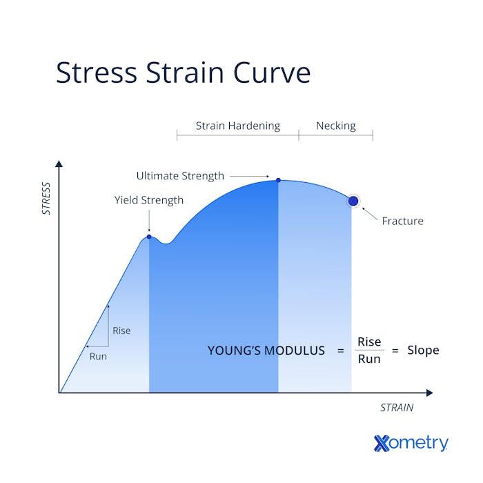
A stress-strain diagram has three stages. In the first stage, the material experiences only elastic deformation. When the applied stress is released, the material returns to its original dimensions. 

Uniform plastic deformation takes place in the second stage. This stage begins at the yield point and continues for as long as the material can continue to strengthen through strain hardening (the same process that occurs in cold forming) with every new increment of the applied load. Eventually, the material's capacity for stable plastic deformation is exhausted. The amount of plastic strain that can be tolerated during this phase tells us a lot about the material's relative brittleness or ductility.

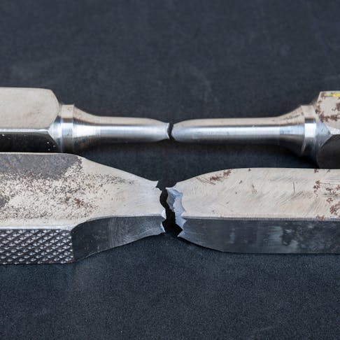
The final stage of a tensile test is referred to as “necking.” This stage occurs after the material’s ultimate tensile stress is reached, and no further strain hardening is possible. Instead of continued, stable deformation, a region of localized deformation forms somewhere in the cross-section of the test specimen. The excessive tensile stresses reduce the material’s dimensions that are perpendicular to the applied force which causes a significant reduction in area. This makes the material have the shape of a “neck”. Once necking begins, the engineering stress of the material decreases while the true stress continues to increase.  The material fractures soon after necking begins.

How To Read the Stress-Strain Graph?

The general steps for how to read a stress-strain graph are described below:

  1. Pick a stress value on the Y-axis.
  2. Trace a horizontal line from the Y-axis until it intersects the stress-strain curve’s line. 
  3. Mark the point where the horizontal line and stress-strain curve line intersect.
  4. Trace a vertical line down from the intersection point to X-axis. The two traced lines should form a sharp, 90° corner.
  5. The stress value chosen from step 1 shows the stress that corresponds to the strain, or deformation, experienced by the test specimen at that point.

The steps above can be used to determine the strain experienced by the test specimen at the moments the yield stress, ultimate tensile strength, and fracture point are reached.

What Are the Different Regions of the Stress-Strain Curve Graph?

Five significant points can easily be picked off a stress-strain curve. The interpretation of each point offers unique insight into the mechanical behavior of a material. The five points are described in detail below:

1. Proportional Limit

The proportional limit refers to the point at the end of the linear portion of the stress-strain curve.All of the deformation up to the proportional limit occurs with one proportionality constant, called Young's modulus. It is calculated as the slope of the line (stress divided by strain) up to the proportional limit. In this region, Young’s modulus can be obtained by calculating the slope of the line. 

2. Elastic Limit

The elastic limit is the observed point on the stress-strain curve where elastic deformation ends and plastic deformation begins. When the applied load is released at any point up to the elastic limit, the material will regain its starting dimensions. In metals, the elastic limit is often difficult to distinguish from the proportional limit and the yield point since the points on the curve are so close to each other. Therefore, the elastic limit is more often used for educational purposes rather than actual characterization of a material’s properties.

3. Yield Point

The yield point is similar to the elastic limit of the stress-strain curve in that it also describes the point where elastic deformation ends and plastic deformation begins. The primary difference between the two is that the yield point is a calculated value that precisely describes the elastic limit, or yield strength of the material. The yield point is determined by offsetting the linear portion of the stress-strain curve by +0.2% along the horizontal (strain) axis. The intersection point of the offset line with the original stress-strain curve is considered the yield strength of the material.

4. Ultimate Stress Point

The ultimate stress point, or ultimate tensile strength, is the highest stress observed on the stress-strain curve. After the ultimate tensile strength is reached, the test specimen begins to “neck.” It’s important to note that while the ultimate stress point is the highest point observed on the stress-strain curve, the actual highest stress is actually the true stress at fracture.

5. Fracture or Breaking Point 

The fracture or breaking point is the point on the stress-strain curve where the test specimen has deformed so much that its microstructure gives and the part fractures.

How To Make a Stress-Strain Curve?

A stress-strain curve is made by conducting a tensile test using a universal testing machine. The testing machine will automatically capture the data to produce a stress-strain curve as the load increases and the specimen deforms. 

What Is the Use of the Stress-Strain Graph?

The stress-strain graph is used to determine various mechanical properties of a material, including elastic modulus, Poisson’s ratio, yield stress, and ultimate tensile strength. These properties help engineers select materials for applications where load-bearing capability is critical.

What Is the Stress-Strain Curve of a Ductile Material? 

The engineering stress-strain curve for a ductile material is characterized by an increasing straight line until the yield point is reached. After the yield point, the function of stress and strain increases non-linearly and peaks when the ultimate tensile strength is reached. Afterward, the engineering stress non-linearly decreases as the strain continues to increase. Eventually, once the material’s strain has become so large, the material fractures. For more information, see our guide on Ductility.

Figure 1 below is an example of a stress-strain curve of a ductile and brittle material:

Slide 1 of 1
ductile and brittle material stress strain curves

Stress-strain curves of a ductile and a brittle material.

Image Credit: https://www.researchgate.net/

What Is the Stress-Strain Curve of a Brittle Material?

The stress-strain curve of a brittle material is a steeply sloped line that shows the stress increasing rapidly with little strain. Unlike ductile materials, the stress-strain curve for a brittle material shows little plastic deformation after the yield stress (yield point) is reached. The material fractures soon after the yield stress.  Figure 1 above is an example of a stress-strain curve of brittle material.

What Is the Difference Between Engineering Stress-Strain and True Stress-Strain?

The differences between engineering stress-strain and true stress-strain are listed below: 

  1. Engineering stress-strain doesn’t take into account the material’s deformation while true stress-strain does.
  2. Engineering strain is the ratio of the change in length to the original length while a true strain is the natural logarithm of the instantaneous length over the original length.
  3. Engineering stress-strain is ideal for determining material performance while true stress-strain is ideal for determining material properties.

What Is the Difference Between Stress and Strain?

The differences between stress and strain are listed below:

  1. Stress is the force per unit area, while a strain is a variation in the length of a dimension over the original length of the dimension.
  2. Stress has units of Pa or psi while a strain is unitless.
  3. The symbol for stress is 𝛔 while the symbol for strain is 𝞊.
  4. Stress is required to cause strain.
  5. Stress cannot be directly measured and is calculated through mathematical relations while a strain can be directly measured.

Summary

This article presented stress-strain curves, explained what they are, and discussed the various calculations needed to create the graph. To learn more about stress-strain curves, contact a Xometry representative.

Xometry provides a wide range of manufacturing capabilities, including 3D printing and other value-added services for all of your prototyping and production needs. Visit our website to learn more or to request a free, no-obligation quote.

Disclaimer

The content appearing on this webpage is for informational purposes only. Xometry makes no representation or warranty of any kind, be it expressed or implied, as to the accuracy, completeness, or validity of the information. Any performance parameters, geometric tolerances, specific design features, quality and types of materials, or processes should not be inferred to represent what will be delivered by third-party suppliers or manufacturers through Xometry’s network. Buyers seeking quotes for parts are responsible for defining the specific requirements for those parts. Please refer to our terms and conditions for more information.

Xomety X
Team Xometry
This article was written by various Xometry contributors. Xometry is a leading resource on manufacturing with CNC machining, sheet metal fabrication, 3D printing, injection molding, urethane casting, and more.