What is GD&T and How is it Used?

GD&T or Geometric Dimensioning and Tolerancing is an important piece of communication between engineers and manufacturers. It is the system used to communicate acceptable levels of deviation from a part’s design dimensions. GD&T is, however, a complex topic that is often misunderstood. This article aims to remove some of the confusion and define some basic GD&T principles.
What is GD&T and How is it Used?
GD&T or Geometric Dimensioning and Tolerancing is an important piece of communication between engineers and manufacturers. It is the system used to communicate acceptable levels of deviation from a part’s design dimensions. GD&T is, however, a complex topic that is often misunderstood. This article aims to remove some of the confusion and define some basic GD&T principles.
Why is GD&T Important?
Engineers must supply GD&T values along with the design itself. Without that tolerancing information, manufacturers are likely to default to their own internal standards. This may seem fine at first, but if the part needs to interface with other parts made under different tolerances, there is a good chance they will not fit or align properly.
In terms of quality control, a part’s acceptance criteria must be clearly defined. If it is not defined, the manufacturer cannot be held responsible for parts that fail to meet tolerance requirements.
What is Tolerance?
Tolerance is simply the deviation from an ideal value that is considered acceptable and which will still allow the completed product to function. This needs to be defined because even the most advanced manufacturing methods cannot consistently achieve an exact value. Many variables caused by tool wear, temperature, fixturing, and operator inconsistencies can affect the production in ways that can’t always be avoided.
What is a Datum?
Before all the different GD&T symbols are defined, it is important to understand the concept of a datum. A datum is a theoretically ideal line, surface, or feature that is used as a reference from which to define the tolerance limit of another feature. For example, in order to specify whether two planes are parallel, one of those planes needs to be assumed as being perfectly aligned. That acts as a reference from which to measure the other plane’s deviation. Once specified, that acceptable deviation becomes the tolerance for both planes as a system.
Explanations for each of the different types of geometric tolerances are given in the sections below.
| Type | Symbol | Description |
|---|---|---|
Type Straightness | Symbol
| Description Typically used to define the permissible deviation on long straight features like the axis of a shaft. |
Type Flatness | Symbol
| Description Defines acceptable deviation between the high and low points on a flat surface. |
Type Roundness | Symbol
| Description Defines acceptable deviation from a perfect circle on parts with circular cross-sections. |
Type Cylindricity | Symbol
| Description Defines both the straightness and roundness tolerances of a cylindrical part. |
Turn Your File Into Parts
| Type | Symbol | Description |
|---|---|---|
Type Angularity | Symbol
| Description Defines the acceptable deviation of an angle with the datum being a straight line or plane. |
Type Parallelism | Symbol
| Description Defines the permissible parallel deviation between a line or plane and a datum line or plane. |
Type Perpendicularity | Symbol
| Description Defines the acceptable deviation of a line or plane that is designed as perpendicular to the datum line or plane. |
FREE CNC Machining Tolerances E-Book
| Type | Symbol | Description |
|---|---|---|
Type Concentricity | Symbol
| Description Defines the acceptable deviation between two cylinders that are designed to be concentric about the same central axis. The datum is the center point. |
Type Coaxiality | Symbol
| Description Defines the permissible coaxial deviation of the central axis of two cylinders. The two axes may form an angle with one another as long as they stay within a theoretical cylinder with a radius equal to the defined tolerance. |
Type Symmetry | Symbol
| Description Defines the acceptable deviation between two planes’ symmetry. This tolerance indicates the deviation of one plane from a theoretical center plane between the features. |

| Type | Symbol | Description |
|---|---|---|
Type Circular Run-Out | Symbol
| Description Defines the acceptable deviation of a cylindrical part at any point on its circumference. |
Type Total Run-Out | Symbol
| Description Defines the acceptable deviation of a cylindrical part at any point on its circumference and along its axis. |
| Type | Symbol | Description |
|---|---|---|
Type Line Profile | Symbol
| Description Defines the acceptable deviation of a curve as viewed from a cross-sectional perspective. |
Type Surface Profile | Symbol
| Description Defines the acceptable deviation of a surface along its entire surface area, i.e. deviations from the ideal shape of the surface are controlled. |
Measuring Tolerance
Various tools and methods are used to measure the above-mentioned tolerances. A dimensional tolerance (i.e. a length or diameter) can often be measured using micrometers or vernier calipers. However, with complex profiles or planar tolerances, it is more efficient to use a CMM (Coordinate measuring machine) to measure multiple points all over with the feature.
What to Look Out for With GD&T
Caution must be exercised when applying GD&T to drawings. One of the biggest mistakes is over-defining the drawing. An over-defined part is just as bad as an under-defined one when it comes to GD&T. Not every single feature needs to be manufactured to exacting tolerances, and as such only critical dimensions and features need to have their tolerances defined and controlled. Over-tolerancing a part will significantly increase its cost because the manufacturer must spend extra time and care to achieve such precision. In addition to this, parts with unrealistic tolerances are more likely to be rejected for failing tolerance checks. Rejections based on non-critical tolerance deviations are not only wasteful but also costly.
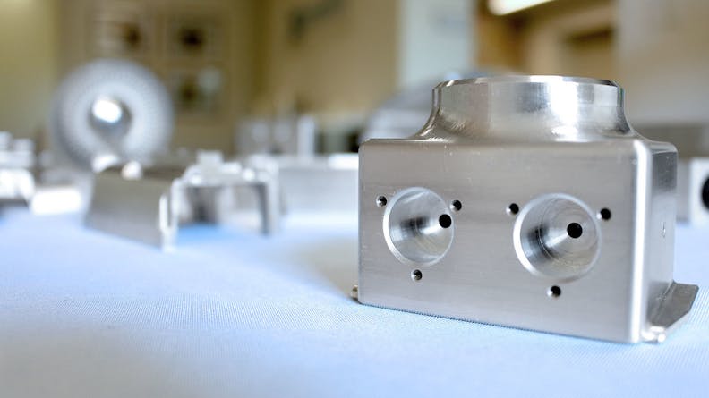
CNC machined parts
When Should GD&T Be Used?
GD&T makes things easier for both the designer and the manufacturer as it clearly defines dimensional requirements. This leaves no room for incorrect interpretations. However, care must be taken when defining tolerances as these values cannot just be arbitrarily chosen. If unsure what tolerances are realistic, a discussion with the manufacturer can usually clear things up. This can prevent costs from spiraling due to over-specified tolerances and unnecessarily complex features. To learn more about how GD&T can ensure that your end product exactly meets your requirements, contact a Xometry expert.