25 Types of Milling Operations


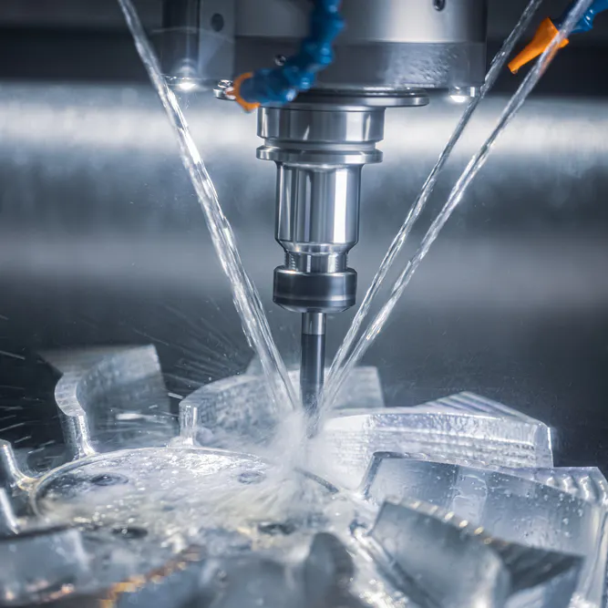
25 Types of Milling Operations constitute the primary methods within material removal in the precision manufacturing sector. 25 Types of Milling Operations employ rotating multi toothed cutters to shape a workpiece into a finished part. Face milling creates flat surfaces on the exterior of a component. Slot milling generates grooves (channels, slots) in solid metal blocks for mechanical fasteners. End milling uses cutting edges on the tip to create internal pockets (cavities, recesses) within housing parts. Thread milling produces internal or external threads through helical tool paths in a CNC machine. Shoulder milling machines a vertical wall alongside a horizontal floor simultaneously at a 90 degree angle. Side milling removes material from the periphery to finish vertical faces on the workpiece. Profile milling follows a programmed path to generate complex 2D or 3D contours (curves, slopes). Saw milling uses thin blades to cut deep slots to separate parts. CAM milling involves computer aided manufacturing software to automate the movement of the cutting tool. Gear milling employs specialized cutters to form the teeth of mechanical gears within power transmission. Angle milling creates surfaces that are neither parallel nor perpendicular to the tool axis (chamfers, V-grooves).
25 Types of Milling Operations allow the creation of intricate three dimensional features on solid workpieces. 25 Types of Milling Operations offer the flexibility needed within different industrial applications (aerospace, automotive, medical). Form milling uses non-flat cutters to reproduce irregular curved shapes in a single pass. Straddle milling employs 2 or additional cutters on an arbor to machine parallel surfaces at once. Plain milling involves a horizontal tool axis to remove a uniform layer from wide metal plates. Gang milling combines different cutters on a single setup to perform multiple operations within high volume parts.
The 25 types of Milling Operations are listed below.
- Face Milling: Face milling is a machining process used to create flat surfaces on the top of a workpiece. The rotating cutter feeds parallel across the surface with its axis oriented perpendicular to the surface to remove a layer of material. The method provides a smooth finish for large surface areas, like Face Milling.
- Slot Milling: Slot milling involves the creation of grooves or channels along the length of a part. The operation uses an end mill or a side cutter to remove material from the center of the solid block. The technique is essential for making keyways like Slot Milling.
- End Milling: End milling utilizes a tool with cutting edges on the tip and sides to create pockets or contours. The cutter moves vertically and horizontally to mill deep into the material for complex features. Engineers use this versatile method for mold making and prototyping, such as end milling.
- Thread Milling: Thread milling is a process for cutting internal or external threads using a specialized rotating tool. The cutter moves in a helical path to generate the correct thread profile on the workpiece. The method offers greater flexibility than traditional tapping for large holes, like Thread Milling.
- Shoulder Milling: Shoulder milling creates two surfaces simultaneously (a vertical wall and a horizontal floor) at a 90 degree angle. The operation is common in the production of square edges on blocks and stepped features. Cutters with a specific corner radius ensure the strength of the shoulder, like Shoulder Milling.
- Side Milling: Side milling involves the removal of material from the side of a workpiece using a tool with teeth on the periphery. The operation is ideal for finishing vertical surfaces and cutting long slots. Machinists use this technique for parts requiring high-accuracy vertical faces, like Side Milling.
- Profile Milling: Profile milling is used to machine complex 2D or 3D shapes along the outer edges of a part. The tool follows a programmed path to create curves, angles, and intricate geometries. The process is necessary for the production of turbine blades and ergonomic handles, such as Profile Milling.
- Saw Milling: Saw milling uses a thin circular blade to cut deep slots or to separate parts from a larger workpiece. The operation involves slow feed rates to prevent the thin tool from bending under pressure. The standard method for cutting narrow grooves in metal plates is saw milling.
- CAM Milling: CAM milling refers to the use of computer-aided manufacturing software to automate the milling process. The program controls the movement of the CNC machine to execute complex tool paths with high repeatability. The technology is the backbone of modern high-speed production, like CAM Milling.
- Gear Milling: Gear milling involves the use of a specialized cutter to form the teeth of a gear. The tool profile matches the space between two adjacent teeth to ensure proper meshing. The method is used for low-volume production and the manufacturing of large gears for heavy machinery.
- Angle Milling: Angle milling creates flat surfaces that are not perpendicular or parallel to the axis of the tool. The operation uses an angular cutter or a tilted workpiece to produce features like V-grooves and chamfers. Machinists employ this technique for dovetail slides and tapered parts, like Angle Milling.
- Form Milling: Form milling uses a cutter with a specific non-flat shape to reproduce that geometry on the workpiece. The operation is used for milling curved profiles (convex, concave) in a single pass. The method is common in the production of intricate architectural hardware and specialty tools like Form Milling.
- Straddle Milling: Straddle milling involves the use of two or more side milling cutters on a single arbor to machine parallel surfaces simultaneously. The operation ensures that the two sides of a part are perfectly parallel and spaced. The highly efficient technique for the production of hex heads and square bolts.
- Plain Milling: Plain milling is a basic operation where the cutter axis is parallel to the surface being machined. The teeth on the periphery of the tool remove material to create a flat horizontal face. The method is also known as surface milling or slab milling for large industrial plates, like Plain Milling.
- Gang Milling: Gang milling uses a series of different cutters mounted on the same arbor to perform multiple operations at once. The combination of tools allows for the creation of complex profiles in a single setup. The technique reduces the cycle time for high-volume parts.
1. Face Milling
Face milling is a fundamental machining operation used to generate flat surfaces on the exterior of a workpiece. The process employs a cutter with teeth on the periphery and the face of the tool. Rotating at high speeds, the cutter moves across the surface of the part to remove a thin layer of material. The axis of the tool remains perpendicular to the surface being machined for optimal accuracy. Large-diameter cutters with multiple inserts allow for the rapid removal of metal from wide areas. Surface finish quality is influenced by the feed rate and the number of cutting edges engaged. High-precision industries (aerospace, automotive) use this method for preparing engine blocks and structural plates. Carbide or ceramic inserts provide the necessary heat resistance for milling tough alloys. Proper tool alignment prevents the formation of ridges on the finished surface of the part. Machinists monitor the chip formation to ensure the cutting conditions remain stable. Face milling is the standard choice for achieving high flatness tolerances for Face Milling.
2. Slot Milling
Slot milling is a specialized operation used to cut channels or grooves into a solid material. The process utilizes an end mill or a side milling cutter to create a specific width and depth. Depth of the slot is achieved through multiple passes of the tool along the same path. Width is determined by the diameter of the cutter or by making several parallel cuts. Chips must be removed efficiently from the narrow channel to prevent the breakage of the tool. Coolant or air blasts help in clearing the metal particles during the cutting action. Rigid workholding is required to minimize the vibration that occurs during deep slotting operations. Keyways and T-slots in mechanical shafts are common examples of this technique. Engineers calculate the side forces on the tool to avoid deflection and dimensional errors. Slotting allows for the creation of interlocking features in complex assemblies. Proper selection of the tool length ensures that the slot reaches the required depth without interference, such as in Slot Milling.
3. End Milling
End milling is a versatile machining process that uses a tool with cutting edges on the end and the circumference. The cutter rotates around its tool axis while moving in three or more directions. This operation is used to create internal pockets, slots, and complex contours on a single part. End mills come in various shapes (square, ball nose, bull nose) to produce different internal geometries. High-speed machining centers utilize this method for the production of molds and dies for the plastics industry. The tool removes material through the interaction of the helical flutes and the workpiece surface. Stability is improved by choosing the shortest possible tool for the required depth. Surface finish is determined by the stepover distance and the feed rate per tooth. Carbide tools with specialized coatings (TiAlN, AlTiN) offer extended life when milling hardened steels. End milling remains a cornerstone of CNC machining for producing intricate mechanical parts with high precision like End Milling.
4. Thread Milling
Thread milling is a process for generating internal or external threads using a rotating multi-point tool. The cutter moves in a helical path to carve the thread profile into the workpiece. This method offers several advantages over traditional tapping (large diameter capability, better chip control). A single thread mill can produce various thread sizes with the same pitch by adjusting the tool path. The operation is ideal for machining threads in hard materials where taps might break. Internal threads are created by entering a pre-drilled hole and moving outward in a spiral motion. Pitch accuracy is maintained by the precise control of the CNC machine axes. Thread milling reduces the risk of part scrappage by allowing for adjustments in the thread fit. Specialized coatings on the tool prevent the adhesion of metal during high-speed cutting. Industrial sectors use this technique for critical fasteners in the aerospace and oil industries. The flexibility of the tool path makes it a preferred choice for complex threading, like Thread Milling.
5. Shoulder Milling
Shoulder milling is a common operation that machines two surfaces at a 90 degree angle simultaneously. The process creates a vertical wall and a horizontal floor on a workpiece. Machinists use this method for producing square edges, steps, and recessed features on blocks. The tool must have a 90 degree approach angle (0 degree lead angle) to ensure the wall remains perfectly vertical. Modern cutters for this operation feature high-performance inserts with multiple cutting edges. Surface finish on the floor and the wall depends on the stability of the tool and the part. Proper chip evacuation is necessary when milling deep shoulders in soft materials. Shoulder milling is often used in the production of mounting brackets and housing components for machines. Engineers specify the corner radius for the shoulder to avoid stress concentrations in the final part. The rigidity of the setup prevents the tool from tilting during heavy side cuts. Efficient material removal makes this technique a staple for Shoulder Milling.
6. Side Milling
Side milling is an operation that removes material from the vertical faces of a workpiece. The tool uses teeth on its periphery to cut into the side of the part. The method is effective for finishing vertical surfaces to tight tolerances. Side milling cutters are often mounted on a horizontal arbor for greater stability during deep cuts. The operation allows for the simultaneous machining of parallel sides when two cutters are mounted on an arbor (straddle milling). Surface finish is influenced by the feed rate and the diameter of the milling tool. High-speed steel or carbide cutters provide the necessary durability for long production runs. Industrial applications include the creation of long slots and the squaring of metal plates. Machinists adjust the spindle speed to match the hardness of the material being cut. Side milling provides the necessary geometry for parts requiring accurate vertical alignment in an assembly like Side Milling.
7. Profile Milling
Profile milling is a machining process used to create complex 2D and 3D shapes along the edges or surfaces of a part. The tool follows a pre-programmed path to generate curves, angles, and intricate contours. The technique is necessary for the production of turbine blades, medical implants, and automotive body molds. Ball nose end mills are often used for 3D profiling to achieve smooth transitions from different planes. The operation requires high-precision CNC machines to maintain the accuracy of the programmed geometry. Surface finish depends on the stepover distance and the resolution of the tool path. Profile milling is used for both roughing and finishing passes on solid metal blocks. Advanced software optimizes the cutting path to reduce cycle times and minimize tool wear. Industrial sectors rely on this method for parts with organic shapes and ergonomic designs. The precision of the profile affects the aerodynamic or mechanical performance of the final component, such as Profile Milling.
8. Saw Milling
Saw milling is a machining operation that uses a thin circular blade to cut deep slots or split parts. The process involves a rotating saw with teeth on the periphery moving through the material. The technique is ideal for cutting narrow grooves that would be difficult for standard end mills. Saw blades are mounted on a rigid arbor to prevent the tool from wobbling during the cut. Slow feed rates are necessary to avoid the bending or breakage of the thin metal blade. The operation is commonly used for parting off components from a larger workpiece in the shop. Coolant delivery is vital for cooling the narrow interface and flushing out metal chips. Saw milling finds use in the production of heat sinks and specialized fasteners. The width of the cut is determined by the thickness of the saw blade. Careful setup ensures that the cut remains straight and perpendicular to the reference surface, like Sawmilling.
9. CAM Milling
CAM milling refers to the use of computer-aided manufacturing software to automate the milling process. The software generates a digital tool path based on the 3D model of the part. A post-processor converts the path into G-code for the CNC machine to execute. This technology allows for the production of highly complex geometries with extreme repeatability. CAM milling reduces the human error associated with manual machine operation. Optimized tool paths minimize the air-cutting time and extend the life of the tool. High-speed machining strategies (trochoidal milling, constant engagement) are programmed using these digital tools. The software calculates the necessary spindle speeds and feed rates for different materials. Industrial manufacturers use CAM systems to manage the production of thousands of identical parts. Real-time simulation of the cutting process prevents collisions and tool breakage on the shop floor. Digital automation is the primary driver of efficiency in modern machine shops like CAM Milling.
10. Gear Milling
Gear milling is the process of cutting teeth into a cylindrical or conical workpiece to create a gear. The operation uses a specialized form cutter with a profile that matches the space between the teeth. Indexing the workpiece between cuts ensures that each tooth is spaced accurately around the circumference. The method is used for manufacturing spur gears, helical gears, and bevel gears for mechanical systems. Gear milling is a preferred choice for low-volume production or for very large industrial gears. The precision of the tooth profile determines the efficiency and noise level of the final gear set. Carbide or high-speed steel cutters provide the necessary hardness for milling tough gear alloys. Proper alignment of the tool and the workpiece is critical for achieving the correct pressure angle. Gear milling allows for the repair and replacement of individual gears in heavy machinery. Reliable power transmission depends on the accuracy of the gear teeth created through the method.
11. Angle Milling
Angle milling is a machining process used to create surfaces that are not parallel or perpendicular to the tool axis. The operation produces features like chamfers, V-grooves, and dovetail slides on a workpiece. The achievement in using a tapered cutter or by tilting the head of the milling machine. Angular cutters have teeth at a specific angles in degrees (45, 60) to match the required part geometry. The technique is essential for parts that must slide or lock together in a mechanical assembly. Precision in the angle is necessary for the proper fit and function of the component. Angle milling is used in the production of tool holders and sliding bed ways for machines. Surface finish is controlled by the feed rate and the stability of the tilted setup. Machinists use this method for both roughing and finishing angular features. Selecting the correct cutter geometry prevents the formation of burrs on the edges of the cut, like Angle Milling.
12. Form Milling
Form milling is an operation that uses a cutter with a non-flat profile to machine complex shapes in a single pass. The tool reproduces its own shape onto the surface of the workpiece. The method is used for milling concave, convex, or irregular curved profiles on metal parts. Custom form cutters are often manufactured to meet specific design requirements for unique components. The process is highly efficient for high-volume production of intricate architectural hardware and tools. Surface finish depends on the precision of the cutter grind and the rigidity of the machine. Form milling reduces the need for multiple passes with different tools to achieve a complex shape. Industrial applications include the production of rifle barrels and decorative trim. Proper spindle speed is necessary to maintain the integrity of the complex tool edge. Form milling provides a consistent way to produce specialized profiles that are difficult for standard tools like Form Milling.
13. Straddle Milling
Straddle milling is a process that machines two parallel vertical surfaces of a part at the same time. The operation uses two side milling cutters mounted on a single horizontal arbor with a spacer. The setup ensures that the two faces are perfectly parallel and have a consistent width. Straddle milling is highly efficient for the production of hex heads, square nuts, and flat sides on shafts. The simultaneous cutting action reduces the total machining time compared to milling each side separately. Rigid arbor support is required to prevent deflection during the dual-sided cut. Machinists use spacers of precise thickness to set the distance from the two cutters. Surface finish is uniform on both sides because the cutting conditions are identical. Straddle milling is a standard technique for mass-producing parts with symmetrical flat features. Proper alignment of the arbor ensures the accuracy of the finished component dimensions.
14. Plain Milling
Plain milling is the basic operation of creating a flat horizontal surface parallel to the axis of the cutter. The process uses a tool with teeth on its periphery, often called a slab mill or a plain mill. This method is used for removing large amounts of material from the top of a workpiece. Plain milling is common in the production of large plates and structural bases for machinery. The width of the cut can match the entire width of the tool for high efficiency. Surface finish is influenced by the feed rate and the diameter of the rotating cutter. High-speed steel or carbide cutters are used depending on the hardness of the metal. Machinists select this method for the initial roughing of raw stock into the required thickness. Plain milling provides a reliable way to achieve a flat reference surface for subsequent operations, like Plain Milling.
15. Gang Milling
Gang milling is a high-efficiency operation where multiple cutters are mounted on a single arbor to perform several cuts at once. The combination of tools allows for the creation of complex profiles or multiple surfaces in a single pass. This technique is ideal for mass production because it significantly reduces the cycle time for each part. Every cutter in the "gang" can have a different diameter and profile to achieve the desired geometry. The arbor must be supported rigidly to handle the high forces from the multiple simultaneous cuts. Machinists carefully calculate the feed rates to accommodate the different cutting conditions of each tool. Gang milling is used in the manufacture of automotive components and complex industrial hardware. Proper setup requires precise spacers and alignment to ensure the accuracy of the final profile. The method is a cost-effective solution for parts with repetitive multi-surface designs.
16. Helical Milling
Helical milling is a process used to create internal or external spiral features on a workpiece. The operation involves the simultaneous rotation and linear movement of the tool or the part. This technique is necessary for the production of helical gears, twist drills, and augers. The angle of the helix is determined by the ratio of the rotational and linear speeds. Helical milling is often performed on specialized machines with a universal head or a dividing head. The tool follows a spiral path to remove material and generate the required lead. Surface finish is critical for the smooth operation of helical components in a gear set. High-precision industries use this method for manufacturing aerospace screws and propulsion parts. Proper selection of the cutter profile ensures the accuracy of the helical flute. Helical milling allows for the creation of complex spiral geometries that are essential for fluid moving and power transmission systems.
17. Plunge Milling
Plunge milling is a high-speed material removal technique where the tool feeds vertically into the workpiece. The operation primarily uses the end-cutting edges of the tool rather than the side flutes. This method is used for roughing out deep pockets and removing bulk material from difficult-to-reach areas. Plunge milling is highly effective because it directs the cutting forces axially into the machine spindle. This orientation reduces the vibration and deflection associated with standard side-cutting operations. Machinists use this technique for machining deep cavities in molds and aerospace components. The process allows for higher feed rates in hard materials like titanium or stainless steel. Plunge milling is often followed by a traditional milling pass to finish the vertical walls of the pocket. Specialized cutters with strong end-teeth are required for this aggressive material removal method. The technique maximizes the productivity of the CNC machine during the initial roughing phase.
18. Trochoidal Milling
Trochoidal milling is a high-speed machining strategy that uses a circular tool path to remove material. The tool moves in a series of loops while advancing through the cut to maintain a constant engagement angle. This method reduces the heat and mechanical stress on the cutting edge during the operation. Trochoidal milling allows for deep axial cuts with small radial engagement for high efficiency. The technique is ideal for milling narrow slots and deep pockets in hard-to-machine alloys. CNC machines with advanced software are required to execute the complex circular tool paths. Tool life is significantly extended because the cutter has more time to cool down between loops. Machinists achieve higher removal rates while maintaining the structural integrity of the tool. Trochoidal milling is a preferred choice for aerospace and medical manufacturing, where precision and tool cost are critical. The strategy ensures stable cutting conditions and high surface quality in demanding applications.
19. High-Speed Milling
High-speed milling is a machining process that utilizes extremely high spindle speeds and feed rates for rapid material removal. The operation operates at speeds several times higher than conventional milling techniques. This method reduces the cutting forces and the amount of heat transferred into the workpiece. High-speed milling produces a superior surface finish and allows for the machining of thin-walled parts. Specialized machines with high-frequency spindles and fast control systems are required for this process. The technique is a standard in the aerospace and mold-making industries for complex parts. Small diameter tools are often used to achieve high precision in intricate details. High-speed milling reduces the cycle time for finishing passes on hardened metal surfaces. Balanced tool holders and high-precision cutters are necessary to minimize vibration at extreme speeds. The process enables the production of parts with mirror-like finishes and tight tolerances. Continuous improvement in tool coatings has expanded the capabilities of high-speed machining for diverse materials.
20. Copy Milling
Copy milling is a technique where the machine follows a physical template or model to reproduce its shape on a workpiece. The operation uses a tracer or sensor to guide the movement of the milling cutter. This method was common for producing complex molds and dies before the widespread use of CNC technology. Copy milling allows for the duplication of organic and irregular shapes that are difficult to program manually. The process is still used for manual repairs and for replicating antique mechanical parts. Surface finish depends on the sensitivity of the tracer and the skill of the operator. Copy milling provides a direct way to transfer 3D geometry from a master part to a new block of material. Industrial applications included the manufacture of shoe lasts and turbine blades. Proper alignment between the model and the workpiece is critical for an accurate reproduction. The technique represents a mechanical predecessor to modern digital scanning and machining.
21. Peripheral Milling
Peripheral milling is an operation where the cutting action occurs on the circumference of the tool. The axis of the cutter is parallel to the surface being machined on the part. This method is used for slab milling and for creating flat surfaces on long workpieces. The teeth on the periphery of the tool remove chips in a curved path as the cutter rotates. Peripheral milling is effective for high-volume material removal from horizontal surfaces. The quality of the finish depends on the feed rate and the diameter of the cutter. Slab mills with helical teeth are often used to reduce vibration and provide a smoother cut. Industrial sectors use this technique for squaring up large blocks of steel or aluminum. Proper workholding is necessary to prevent the part from lifting during the climb or up-milling process. Peripheral milling remains a core operation for preparing flat plates in heavy-duty manufacturing shops.
22. Slab Milling
Slab milling is a form of peripheral milling used to machine large flat horizontal surfaces. The process employs a wide cylindrical cutter with teeth on its outer surface. This operation is highly efficient for removing a uniform layer of material from wide metal plates. Slab milling is often performed on horizontal milling machines for greater stability and power. The width of the cutter often exceeds the width of the workpiece to finish the surface in one pass. Machinists use this method for the initial roughing of raw stock into flat plates. The feed rate and spindle speed are optimized to handle the large contact area of the tool. Surface finish is controlled by the tooth geometry and the rigidity of the machine arbor. Slab milling is a staple in the production of machine beds and structural industrial components. The process ensures high flatness and consistent thickness across the entire workpiece.
23. Keyway Milling
Keyway milling is a specialized operation used to cut slots into shafts or hubs for the installation of keys. The process creates a precise rectangular or woodruff-shaped recess to allow for power transmission. This technique is essential for securing gears, pulleys, and sprockets to rotating shafts in mechanical systems. End mills or woodruff cutters are used to achieve the specific dimensions required for the key. Precision in the width and depth of the keyway is necessary for a secure and vibration-free fit. Keyway milling is often performed on vertical mills or specialized keyseating machines. The operation requires rigid setups to prevent the tool from wandering during the cut. High-precision industries rely on this method for the assembly of drive trains and industrial motors. The length of the keyway is controlled by the travel of the machine table. Proper alignment ensures that the keyway is perfectly centered on the diameter of the shaft.
24. Pocket Milling
Pocket milling is the process of removing material from within a bounded area on a workpiece to create a cavity. The operation uses an end mill to create the desired depth and shape of the internal pocket. This technique is a common requirement for weight reduction and for housing internal mechanical components. CNC machines use various tool path strategies (spiral, zig-zag) to clear the material efficiently. The corners of the pocket are determined by the radius of the milling cutter used. Deep pocket milling requires efficient chip evacuation and coolant delivery to prevent tool breakage. Surface finish on the floor and walls of the pocket depends on the finishing passes and tool stability. Aerospace and electronics industries use this method for complex housings and structural frames. Selecting the correct tool diameter ensures that the pocket geometry is achieved without unnecessary tool changes. Pocketing is a fundamental operation in the production of modern lightweight components.
25. Engraving Milling
Engraving milling is a high-precision operation used to cut letters, numbers, or logos into the surface of a part. The process utilizes small-diameter tools with sharp points or ball noses to create fine details. This technique is necessary for part identification, branding, and decorative purposes on various materials. CNC machines execute the programmed text or designs with high accuracy and consistency. Engraving is often performed on the final finished surface of the part as a last step. High spindle speeds are required for the small tools to prevent the breakage of the delicate tips. The depth of the engraving is usually shallow to minimize the impact on the structural integrity of the component. Industrial sectors use this method for labeling medical instruments and aerospace parts. Proper selection of the tool angle (tip angle) ensures the legibility of the engraved characters. Engraving milling provides a permanent and durable way to mark mechanical components in the shop.
What Is Milling?
Milling is a versatile subtractive manufacturing process that uses rotating cutters to remove material from a workpiece. The operation involves the use of multi-toothed tools that rotate at high speeds to chip away at the metal or plastic surface. Workpieces are secured to a movable table that feeds the part into the rotating cutter. The process allows for the creation of diverse shapes (flat planes, slots, pockets, complex 3D contours) on a single machine. Milling is a cornerstone of modern manufacturing due to its high precision and ability to handle various materials. Vertical and horizontal milling machines are the two primary categories used in the industry. Computer numerical control technology has revolutionized the process by automating the tool movements for extreme repeatability. Engineers specify the milling operations to achieve tight tolerances and smooth surface finishes for industrial parts. The flexibility of the process makes it ideal for both prototyping and mass production of mechanical components.
What Is the Importance of Milling?
The importance of milling lies in its ability to produce complex and precise parts that other processes cannot achieve. The technique provides the necessary accuracy for critical components in the aerospace, medical, and automotive sectors. Milling allows for the creation of intricate internal features and smooth external surfaces on solid materials. The process is essential for making the molds and dies used in mass-production casting and injection molding. High repeatability ensures that thousands of identical parts can be manufactured with consistent quality. Milling handles a wide range of materials from soft plastics to hardened alloys and exotic metals. The versatility of the equipment reduces the need for multiple machines in a production line. Modern CNC milling offers high efficiency and rapid turnaround times for custom parts and prototypes. Reliability in mechanical assemblies depends on the tight tolerances achieved through professional milling operations. The process remains a vital driver of innovation and productivity in global manufacturing.
What Are the Uses of Milling?
Milling finds use in the production of a vast array of everyday and specialized industrial products. The process is used to manufacture engine components (pistons, cylinder heads) for the automotive industry. Aerospace manufacturers rely on milling for structural airframe parts and turbine components made from titanium. In the medical field, milling produces custom orthopedic implants and high-precision surgical instruments. The electronics sector uses the process for machining heat sinks and complex housings for various devices. Milling is also used in the creation of architectural hardware, custom tools, and decorative metalwork. Heavy industry employs the technique for making large gears and machine bases for factory equipment. Prototyping shops use milling to create functional models for testing before mass production. The ability to create parts with precise dimensions makes it a preferred choice for high-tech manufacturing. Milling continues to be a primary method for shaping the components of the modern world in every industrial sector.
How To Choose a Type of Milling?
Choosing a type of milling depends on the final geometry of the part and the material being machined. Engineers first evaluate the surface requirements (flatness, slots, pockets) to determine the necessary tool path. Face milling is selected for large flat areas, while end milling is used for internal features. Material hardness influences the choice of cutter material and the required spindle speed of the machine. The complexity of the design dictates whether 3-axis or multi-axis milling is necessary for production. Cost is another factor, as some operations are faster and more economical for high volumes. Surface finish specifications guide the selection of tool geometry and finishing strategies. Precision requirements determine the type of machine and the quality of the tooling needed for the job. Technicians also consider the quantity of parts, as some setups are more efficient for mass production. Proper selection ensures the efficiency and the quality of the final mechanical component.
"Translating functional system requirements into manufacturable components requires balancing geometric complexity with fundamental material behavior. True engineering efficiency is realized when product design intentionally accounts for process capabilities, ensuring part performance while preventing costly manufacturing redesigns."
What Is the Most Popular Type of Milling?
End milling is the most popular type of milling due to its extreme versatility and wide range of applications. The process uses a tool that can cut in both axial and radial directions simultaneously. End milling allows for the creation of slots, pockets, profiles, and complex 3D shapes with a single tool. Machinists use this method for everything from basic roughing to high-precision finishing on various materials. The wide availability of different end mill shapes (square, ball, radius) increases the flexibility of the operation. CNC machining centers utilize end milling as the primary strategy for most modern manufacturing tasks. The process is essential for industries like aerospace and mold-making, where complex geometries are the standard. Efficiency and ease of programming make it a preferred choice for both manual and automated shops. Most mechanical parts require at least one end milling operation during the manufacturing process. The ability to perform multiple tasks makes it a staple in the industry.
What Is the Cheapest Type of Milling Operation?
Plain milling is often considered the cheapest milling operation for producing simple flat surfaces on a large scale. The process uses basic cutters that are less expensive to manufacture and maintain than complex multi-axis tools. Plain milling on a horizontal arbor provides high material removal rates with low energy consumption. The simplicity of the setup reduces the labor time required for machine programming and part handling. Standard rectangular workpieces can be machined quickly with high repeatability for general-industrial uses. Low-cost materials like mild steel or aluminum are easily shaped using this fundamental technique. Plain milling requires less advanced machinery compared to high-speed or 5-axis operations. The durability of the plain milling cutter leads to a lower cost per part over long production runs. Choosing this method for basic flat features helps in minimizing the total production cost for simple mechanical components. Efficiency in bulk material removal makes it an economical choice for the shop.
What Is the Most Expensive Type of Milling Operation?
Five-axis profile milling is generally the most expensive type of milling operation used in the industry. The process requires advanced multi-axis CNC machines that represent a significant capital investment for the manufacturer. The complexity of the five-axis tool path necessitates specialized software and highly skilled programmers to manage the operation. Longer cycle times for intricate 3D geometries increase the hourly cost of the machine time. Specialized tooling (high-performance carbide, custom coatings) adds to the total expense of the production run. Five-axis milling is used for critical components (turbine blades, medical implants) where extreme precision is mandatory. Maintenance costs for high-precision multi-axis equipment are also significantly higher than for standard mills. The rigorous testing and quality control required for these parts further increase the final price. Despite the cost, this method is necessary for parts that cannot be manufactured through simpler means. Efficiency in producing finished parts in a single setup offsets some of the initial high expenses.
What Type of Milling Operation Is Most Accurate?
High-speed finishing milling is typically the most accurate type of milling operation for achieving tight tolerances. The process utilizes high spindle speeds and fine feed rates to minimize the cutting forces on the tool. Reduced vibration and heat generation allow for extreme precision in the final dimensions of the part. High-speed machining centers feature advanced control systems that manage the tool path with micrometer-level accuracy (typically ±0.0001" to ±0.0002") Small-diameter, high-precision tools are used to reach intricate details and maintain sharp corners. Surface finishes achieved through this method can reach mirror-like quality with minimal roughness. This technique is mandatory for the production of aerospace components and high-quality optical molds. The stability of the machine and the environment (temperature control) plays a critical role in the final accuracy. High-speed finishing ensures that the part meets the most demanding engineering specifications for fit and function. The precision achieved through this method reduces the need for secondary grinding or polishing operations.
What Is the Difference Between a Face Mill and an End Milling?
Face milling and end milling differ in the orientation of the tool and the location of the cutting action. Face milling uses a large-diameter cutter that removes material from the top surface of a workpiece. The primary cutting edges are located on the periphery while face teeth finish the surface. End milling utilizes a cylindrical tool that can cut with both its end and its periphery. The process allows the end mill to create vertical walls, internal pockets, and complex slots. Face mills are preferred for the rapid removal of metal from large areas with high flatness. End mills offer greater versatility for intricate features and 3D contours on a single part. Face milling is often the initial step in preparing a part for the more detailed end milling operations that follow in the production cycle. The choices depend on the specific geometry of the feature being machined between a face mill and an end mill.
The difference between face milling and end milling is shown in the table below.
Can the Same Milling Cutter Be Used for Multiple Milling Operations?
Yes, the same milling cutter can be used for multiple milling operations depending on its design. A standard end mill is the most common example of a tool that performs diverse tasks in the shop. The single cutter can create slots, machine vertical shoulders, and mill internal pockets in a single setup. Ball nose end mills are used for both roughing 3D shapes and providing a fine surface finish. The versatility of the tool reduces the number of tool changes required during the manufacturing process. Some high-performance cutters are designed for both plunging and lateral milling to improve efficiency. Changing the tool path in the CNC program allows one tool to achieve different geometric results. Engineers select multi-purpose tools to save on tooling costs and decrease the total cycle time. Proper selection of the tool coating and geometry ensures that it remains effective across various operations. Flexibility in tool use is a key factor in modern machining productivity.
What Milling Cutter Has Helical Flutes on Its Surface?
End mills and slab mills are the primary milling cutters that feature helical flutes on their surface. The helical design allows the cutting edges to engage the workpiece gradually rather than all at once. The configuration reduces the impact force and the vibration that occurs during the cutting process. Helical flutes also facilitate the efficient removal of metal chips from the cutting zone. The angle of the helix determines the smoothness of the cut and the direction of the axial forces. Standard end mills typically have helix angles from [30 to 45] degrees for general-purpose machining. High-helix tools are used for soft materials like aluminum to prevent chip clogging in the flutes. Slab mills use large helical teeth to provide a continuous cutting action across wide horizontal surfaces. The helical geometry is essential for achieving high surface quality and extending the life of the cutting tool during high-speed operations.
Is CNC a Type of Milling Operation?
No, CNC is not a type of milling operation but rather a method of controlling the machine. Computer Numerical Control refers to the automated system that manages the movement and speed of the milling tool. Milling is the physical process of material removal using a rotating cutter, regardless of the control method. CNC technology is applied to various milling operations (face milling, end milling, slotting) to improve accuracy and repeatability. Manual milling involves a human operator turning handwheels to move the machine table. CNC milling uses a programmed digital code to execute the tool paths with extreme precision. Most modern industrial milling is performed on CNC machines due to the high efficiency and complexity they can handle. The combination of CNC and milling allows for the production of parts that are impossible to create by hand. Understanding the distinction is important for selecting the right manufacturing process. Automation remains the primary driver of productivity in the modern machining industry.
What Factors Affect Cutting Conditions in Milling Machining Operations?
The factors that affect cutting conditions in milling machining operations are listed below.
- Cutting Speed and Feed Rate: Cutting speed refers to the tangential surface speed of the cutter (Vc), while feed rate is the relative speed at which the part moves into the tool. These settings are determined by the material hardness and the tool diameter. Incorrect values lead to excessive heat or the breakage of the cutting edges. Proper balance is required for efficient material removal and smooth finishes.
- Tool Material and Geometry: The type of material used for the tool (carbide, high-speed steel) affects its hardness and heat resistance. Tool geometry (number of flutes, helix angle) determines how the chips are formed and removed. Selecting the right tool for the specific metal ensures stable cutting conditions. Proper coatings reduce friction and prolong the service life of the tool.
- Workpiece Material and Rigidity: Harder materials require slower speeds and more robust tools to prevent premature wear. The rigidity of the part setup minimizes the vibration and deflection that occur during the cut. Unstable workholding leads to poor surface quality and dimensional errors in the final part. Engineers consider the mechanical properties of the metal before starting the machining process.
How Do Cutting Speed and Feed Rate Affect Milling Surface Finish?
Cutting speed and feed rate affect milling surface finish by their direct impact on the roughness and quality. Higher cutting speeds generally improve the finish by reducing the size of the chips and the cutting forces. The increased speed allows the tool to shear the material more cleanly with less friction. A lower feed rate per tooth results in a smoother surface by reducing the distance between the individual cutter marks. Slowing the feed rate during a finishing pass is a standard practice for achieving mirror-like qualities. If the feed rate is too high, the surface will show visible ridges and patterns from the tool. Proper synchronization of the speed and feed is necessary to avoid the buildup of heat that can warp the surface. Machinists use established formulas to calculate the optimal settings for different material and tool combinations.
What Role Does Milling Machine Tooling Play in Machining Process Performance?
Milling machine tooling is the primary factor that determines the efficiency and accuracy of the machining process. High-quality tools allow for faster material removal rates and better surface finishes on the part. The rigidity of the tool holder prevents deflection and vibration during heavy-duty cutting operations. Advanced tool coatings (TiAlN, DLC) provide the necessary heat resistance for milling difficult alloys. Proper tooling selection reduces the frequency of tool changes and the associated machine downtime. The geometry of the cutter (flute count, helix angle) influences chip evacuation and the total cutting force. Using the correct tool for a specific operation (roughing vs finishing) ensures the best possible result for the component. Modern tooling systems offer high repeatability and precision for complex CNC operations. Investing in high-performance cutters leads to lower costs per part over long-term production. The interaction between the tool edge and the metal surface is the foundation of the subtractive manufacturing process. Reliable performance starts with the selection of the appropriate milling machine tooling.
Does the Type of Milling Machine Affect Which Milling Operations Can Be Performed?
Yes, the type of milling machine determines the range of operations that can be successfully executed. Vertical milling machines are ideal for end milling, slotting, and drilling because the spindle is perpendicular to the table. Horizontal milling machines excel at heavy slab milling and side milling using cutters mounted on an arbor. Five-axis machines offer the greatest flexibility by allowing the tool to reach almost any surface of a part in a single setup. Some specialized machines are designed specifically for gear cutting or high-speed engraving. The rigidity and power of the machine also limit the size of the cutters and the depth of the cuts. Small desktop mills cannot perform the heavy-duty roughing operations required for large steel blocks. Choosing the correct machine for the job ensures the efficiency and accuracy of the manufacturing process. Machine configuration is a primary consideration when planning the production of complex mechanical parts in the shop.
What Are the Industrial Applications and Uses of Milling Machine Operations?
The industrial applications and uses of milling machine operations are listed below.
- Automotive Industry: Milling is used to produce engine components (blocks, heads, pistons) and transmission parts with tight tolerances. The process ensures the high reliability and performance required for modern vehicle systems. High-volume production lines use specialized mills for the rapid manufacture of thousands of identical parts. Precision milling allows for the creation of complex cooling passages and structural features.
- Aerospace Sector: The aerospace industry uses milling to shape large structural airframe components from solid aluminum and titanium blocks. The parts must be lightweight yet extremely strong to handle the stresses of flight. Five-axis milling is common for creating the complex curved surfaces of turbine blades and wing structural spars. Extreme accuracy is mandatory for the safety and efficiency of the aircraft.
- Medical Manufacturing: Medical device companies utilize high-precision milling to create orthopedic implants (knees, hips) and surgical instruments. The materials used (cobalt chrome, titanium) require specialized cutters and high-speed machining strategies. The part must meet strict biocompatibility and surface finish standards for human use. Small-scale milling machines are often used for the intricate details of dental crowns and prosthetics.
How Is Milling Used in Metal Manufacturing and Metalworking Processes?
Milling is the primary subtractive process used in metal manufacturing to create parts with precise dimensions and geometries. The operation removes excess material from solid metal stock to reach the final shape required by the design. Metalworking shops use milling for both the initial roughing of large plates and the final finishing of critical surfaces. The process allows for the creation of internal features (pockets, threaded holes) that are essential for mechanical assemblies. Milling is often used in conjunction with other metalworking techniques (turning, grinding, welding) to complete a part. Specialized cutters handle a wide variety of metals from soft aluminum to hardened tool steels. Modern CNC technology allows for the automation of complex metal shapes that were once impossible to produce. The high material removal rate of milling makes it an efficient choice for bulk manufacturing. Surface quality achieved through milling reduces the need for expensive secondary operations in the production cycle. Every metal component in a machine typically undergoes at least one milling step.
Which Types of Milling Machines Are Best for Industrial and Heavy-Duty Applications?
The types of milling machines best for industrial and heavy-duty applications are listed below.
- Horizontal Machining Centers: Horizontal mills are preferred for heavy-duty work because the spindle orientation allows for better chip evacuation. The machines often feature high-torque spindles and robust arbors for large slab and face milling operations. The horizontal configuration is ideal for machining multiple sides of a part using a tombstone fixture. Efficiency is high for bulk material removal in the automotive and heavy equipment industries.
- Bed-Type Milling Machines: Bed mills feature a vertical-only moving spindle head and a table mounted directly on the machine bed for maximum support. The design is much more rigid than knee-type mills and can handle significantly heavier workpieces. Heavy-duty manufacturers use bed mills for machining large engine blocks and structural frames. The lack of a movable knee increases the stability of the machine under heavy cutting loads.
- Gantry Milling Machines: Gantry mills use a large overhead structure to move the spindle over a massive, stationary work table. The machines are the standard for the aerospace and energy sectors for machining very large components (wings, turbine housings). The design allows for the processing of parts that are dozens of feet long with high precision. Gantry mills provide the ultimate combination of scale and accuracy for the heaviest industrial tasks.
Is CNC Milling More Efficient Than Manual Milling for Production Applications?
Yes, CNC milling is significantly more efficient than manual milling for production applications due to automation and precision. The computer-controlled system executes complex tool paths at high speeds without the need for constant human intervention. CNC machines can operate continuously (24 hours a day) with high repeatability and minimal downtime. Manual milling depends on the skill and speed of the operator, which varies throughout the day. A single CNC program can produce thousands of identical parts with exact dimensions every time. Multi-axis CNC centers can perform multiple operations in a single setup to reduce part handling. Manual machines require a human to manually change tools and reposition the part for every new feature. Manual milling is useful for quick repairs and simple one-off parts, and it cannot compete with the volume and complexity of CNC milling.
Summary
25 Types of Milling Operations provide the fundamental capabilities required for modern subtractive manufacturing across all industrial sectors. The shift of basic face milling to complex five-axis profiling allows for the creation of precise and functional mechanical parts. The evolution from manual machines to advanced CNC technology has significantly increased the efficiency and accuracy of the process. Choosing the right operation and tooling is essential for balancing production costs and part quality for the customer. Milling handles a diverse range of materials and geometries to meet the demanding requirements of aerospace, medical, and automotive engineering. High-performance cutters and stable machinery are the foundation of a successful machining operation in the shop. Understanding the differences among various milling methods helps engineers optimize the manufacturing workflow for any given project. Reliability in the final assembly starts with the precision achieved through these professional milling processes. Continued innovation in tool coatings and software ensures that milling remains a vital driver of global productivity.
How Xometry Can Help
Xometry provides an extensive range of manufacturing solutions including high-precision milling services for any industrial application. The platform connects customers with a global network of thousands of vetted machine shops with advanced capabilities. Users can upload 3D models to receive instant quotes and lead times for their custom parts. Xometry supports various milling operations from simple 3-axis tasks to complex 5-axis aerospace projects. The service handles a wide variety of materials (metals, plastics, composites) to meet the specific needs of any project. Quality assurance processes ensure that every part meets the required tolerances and surface finish specifications for the user. Scalable production options allow for both rapid prototyping and high-volume manufacturing of mechanical components. Xometry simplifies the supply chain by providing a single point of contact for all machining requirements. Professional support teams are available to assist with design for manufacturing feedback to optimize part production. Digital procurement through Xometry enhances the efficiency of sourcing custom-machined parts.
Disclaimer
The content appearing on this webpage is for informational purposes only. Xometry makes no representation or warranty of any kind, be it expressed or implied, as to the accuracy, completeness, or validity of the information. Any performance parameters, geometric tolerances, specific design features, quality and types of materials, or processes should not be inferred to represent what will be delivered by third-party suppliers or manufacturers through Xometry’s network. Buyers seeking quotes for parts are responsible for defining the specific requirements for those parts. Please refer to our terms and conditions for more information.