Milling is a type of machining that has its origins in food preparation. Originally, people milled grain into flour using quern stones: a set with one flat stationary stone, and one rotating stone with a hole in the middle. The grain was fed into the hole, ground down by the rotating quern (a basic hand mill), and exited the set-up as flour. Though extremely primitive, this is the origin of all rotating machinery. These days, the term mill indicates the rotating tool-cutting machines for wood, metal, plastics, and stone.
Milling in Machining
The manufacturing industry mostly uses milling to cut materials from a workpiece, and make lots of different items in many sizes and shapes. Milling machines are highly precise and have very tight tolerances. That’s important for industries where accuracy is essential; aerospace, for instance, more often than not needs lightweight and complex parts for its flight-engineered products. Parts such as airframe components, controls, jet and rocket engine components, and flight-surface actuator parts all come from milling. Similarly, being able to process a variety of material that is both biodegradable and easily sterilized make milling the common choice for surgical tools and medical implants.
Milling allows you to make all sorts of shapes and contours in materials that can otherwise be difficult or even impossible with other machining methods. Lots of materials are compatible with machining, including metals like aluminum, steel, brass, and copper; acrylic, Kevlar, polycarbonate, nylon, Delrin, fiberglass, hardwood, softwood, ceramics, cermets, graphite, and glass, just to name a few.
Versatility of material is just one advantage of milling, along with the size, quality, and precision it provides. It’s super quick, and doesn’t produce much waste, either. It’s also economical and simple to automate. The milling process isn’t ideal if you need to cut hardened materials, and heavier cuts understandably take longer to do. The machines, although they’re clearly useful, can be challenging to use, and tend to suffer with wear and tear. They also generate a good amount of heat, chatter, and vibration.
How Milling Works
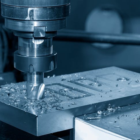
At its most basic level, a hardened steel or exotic material cutter rotates against the workpiece to remove material. Most commonly the cutter moves on a fixed X-Y-axis, but can be adjusted to move on the Z-axis as well. A 3-axis milling machine as described is the most basic option, but there are 4, 5, and even 7-axis machines available.
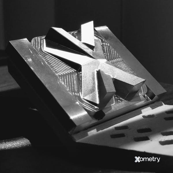
The process starts by loading the workpieces, then clamping them to the table with something like a vise. This will prevent accidental offset cuts and drifting or broken parts while you’re working on the piece. Next, you select the proper tool for the material and project at hand. Then you have to set up the machine, adjusting things like spindle speed and cutting depth. Once all that is set, you’re ready to start milling. The process can be automated or manual, but both need care and attention for an ideal finished product. Here’s an example of a part made via milling by the Xometry team.

The first thing to do is rough up the material by making deep cuts that remove large, unwanted chunks so that it starts to take the form of the final part. It’s then semi-finished with slower, shallower, and more precise cuts, before moving onto full finishing. Once the milling is done, you have to unload the workpiece. Typically people clean the machine at this point too. After you unload the piece, check that the measurements and surface quality meet expectations. Finally, you’ll have to do some post-processing, which could include steps like deburring, heat treatments, surface coatings, and storing. Xometry’s suppliers take all these steps on behalf of our customers, should their projects require it.
Types of Milling Machine
There are loads of different milling machine types, and we briefly explain the most common in the table below. Most of these machines are available through Xometry’s supplier network.
| Milling Machine | Spindle Orientation | Features | Applications |
|---|---|---|---|
Milling Machine Vertical | Spindle Orientation Vertical | Features Simple design | Applications Face milling, end milling, best for smaller workpieces |
Milling Machine Horizontal | Spindle Orientation Horizontal | Features Cuts along entire length of workpiece | Applications Mass production, heavy-duty cutting |
Milling Machine Universal | Spindle Orientation Either | Features Swiveling table for easy angle adjustment | Applications Versatile, angular cuts |
Milling Machine Turret | Spindle Orientation Vertical | Features Rotating turret for multi-tool use | Applications Precision, repetitive cuts |
Milling Machine Bed | Spindle Orientation Vertical | Features Moving spindle, stationary bed | Applications Large, heavy workpieces |
Milling Machine Knee | Spindle Orientation Vertical | Features Adjustable knee | Applications Quick and easy height changes |
Milling Machine Ram | Spindle Orientation Both | Features Movable ram, can cut in both directions | Applications Various types of cuts |
Milling Machine Planer | Spindle Orientation Horizontal | Features Moving work table, vertical cutter adjustment | Applications Large flat surfaces, precise cuts |
Milling Machine CNC | Spindle Orientation Either | Features Automated, highly precise | Applications Minimal manual labor, complex designs |
Milling Machine Gantry | Spindle Orientation Either | Features Bridge structure, spindle moves across workpiece | Applications Large, heavy workpieces |
Common Milling Methods
Climb and conventional are the two most widely used milling methods in manufacturing. Climb milling (sometimes called “down milling”) rotates the tool against the direction of the workpiece’s motion, so the tool moves in the same direction as the material feed, with the cutter climbing over the workpiece. This method offers smooth surfaces with hardly any material deviation, and it won’t overheat or quickly wear out your tools, either. It’s best for high-quality parts and thinner sections and can help you better manage chips.
Conventional milling (or “up milling”) has the cutting tool rotating in the same direction as the workpiece, which makes the tool move in the opposite direction of the material feed. It works best with more malleable materials, and offers a faster machining process. It also results in a rougher finish, reduced precision, and increased tool wear.
Factory Floor Machining Precautions
You absolutely have to closely follow safety rules when using a milling machine. A strict maintenance schedule will help you keep on top of things and notice potential hazards, like damage, loose parts, and general wear and tear. Top of your checklist should be making sure all the safety features, like the stop buttons, are working properly, and that you—and everyone who uses the machine — know exactly where they are and how to use them. All technicians have to be well trained, particularly in the operation process, safety procedures, and possible dangers. It should go without saying, but please don’t sidestep the guards and interlocks—these are here for your safety.
The first thing on your milling to-do list should be personal protective gear. This includes safety glasses, hearing protection, gloves, etc.) Your work area should be clean and tidy, and well-lit. The settings, including the cutting speed and feed rate, will need to be adjusted according to the type, size, and thickness of the material you’re working on, and the workpiece should be clamped securely in place so that it doesn’t move around during the process. Keep hands and hair far away from moving parts at all times, and when you’re changing tools, make sure to switch the machine off first.
Milling vs. Cutting in Machining
Generally, all milling involves cutting with rotating tools that pass over a part. It precisely removes pieces of material as the teeth cut through the billet to “extract” the required part from a blank. Cutting as a standalone process usually involves a broaching type action, during which teeth pass over the surface of a part in a linear motion to remove an elongated kerf the entire length of the part, resulting in a slot being cut that separates the material into two parts. The motion can be reciprocating, like a saw blade using a cut and return sequence, or continuous. The continuous cut can come from a bandsaw blade that passes the material in one direction, or it can be a circular slitter/wheel saw that moves the part in a linear motion as it rotates. The distinction between milling and cutting isn’t super clear in many cases, because milling cutters are often used for simple cutting jobs. That said, linear cutters aren’t typically used in milling operations.
Milling vs. Swiss Machining
Swiss machines are, in reality, early versions of multi-axis machining centers, developed for the mass production of clocks and watches in the 19th century. The addition of cutter rotation that can work alone or in combination with the part rotation in the chuck allowed the production of flat and square features on otherwise cylindrical workpieces, held still in the chuck and cut by the movement of rotating cutters. It wasn’t until the 1970s that lathes began to encompass these types of combined features, and it’s taken the development of 6-axis CNC machines to truly compete with the functionality of Swiss machines.
How Xometry Can Help
Xometry works with more than 10,000 manufacturing partners, so whatever material or service you need, including CNC milling, we’ll be happy to help. You can either reach out to one of our reps, or get started straight away by uploading your designs to the Xometry Instant Quoting Engine®.
Copyright and Trademark Notice
- Delrin® and Kevlar® are registered trademarks of DuPont.
Disclaimer
The content appearing on this webpage is for informational purposes only. Xometry makes no representation or warranty of any kind, be it expressed or implied, as to the accuracy, completeness, or validity of the information. Any performance parameters, geometric tolerances, specific design features, quality and types of materials, or processes should not be inferred to represent what will be delivered by third-party suppliers or manufacturers through Xometry’s network. Buyers seeking quotes for parts are responsible for defining the specific requirements for those parts. Please refer to our terms and conditions for more information.


