Fracture Strength: What it is and How It Works


A material’s fracture strength defines the maximum stress or load it can withstand before a fracture occurs. It is a critically important mechanical property, as it characterizes the material's resistance to failure under a range of applied forces and loading modes. Fracture strength is typically determined through a variety of test procedures, and each of these various test methods defines one version of fracture toughness. These are: tensile test, compression test, flexural test, and impact test.
A deep understanding of the strength limits and failure modes of materials is key to many aspects of good product design, optimized product function, and safety (particularly factor of safety, FoS).
This article will further discuss fracture strength, how it works, the tests used to determine a material’s fracture strength, and the factors that affect it.
What Is Fracture Strength?
Fracture strength refers to the maximum stress or loading that a material can withstand before it undergoes a catastrophic failure by fracture. It defines the material's ability to resist crack-based failure under an applied load. Fracture strength is typically expressed in units of pressure, such as pounds per square inch (psi) or pascals (Pa). The fracture strength of a solitary, blended, or composited material is a function of its inherent properties such as crystal lattice composition, alloy/composite structure, and manufacturing processes. Various materials exhibit widely varying levels of fracture strength due to their atomic arrangement and interatomic bonding.
Brittle materials like concrete, gray cast iron, and ceramics tend to possess high compressive strength but low fracture strength. They can withstand high compressive forces but are easily subject to fracture under tensile or bending stresses. Ductile materials like mild steel, aluminum, and many polymers encompass relatively lower compressive strength but higher fracture strength. This enables them to deform plastically before failure by cracking.
Fracture strength is significantly altered by various factors, including: temperature, rate of loading, presence of defects or flaws, and the nature of the applied stress (tensile, compressive, shear, etc.). Engineers and material scientists analyze fracture strength to optimize and select materials suitable for particular applications, based on an understanding of expected loads and required factors of safety to prevent catastrophic failures.
What Are the Modes of Fracture in Materials?
Fracture strength is designated according to the mode of applied loading: tensile, compressive, or bending. The mechanics of tensile, compressive, and bending fractures involve various stress distributions and failure mechanisms.
Tensile fracture occurs when a material is subjected to an external force that tensions it along a single axis of load, up to the failure point. It is typically characterized by a separation or rupture of the material on a plane perpendicular to the applied tensile load. Initially, the material undergoes elastic deformation, which elongates the test item in the direction of applied tensile stress. This deformation is fully recovered, once the load is removed—i.e., the component returns to its original dimensions.
As the applied load increases, localized regions of the material start to undergo necking, which is a reduction in cross-sectional area. The material stretches along crystal boundaries via a slipping mechanism and may undergo structural changes in this phase, such as work hardening.
Eventually, the load increases to the limit of the material's strength, such that any further extension requires no additional force and may require decreasing force. At some point, after this peak force is reached, the necked region reaches a critical point at which the material can no longer withstand the applied load. This leads to rapid propagation of the fracture across the entire cross-section. This force is referred to as the ultimate tensile strength (UTS)
A compressive fracture occurs when a material is subjected to an external force that compresses it along the loaded axis. It is characterized by a bulging/crushing and eventual crumbling or tearing of the material. This often results in multiple fractures and potential fragmentation. The applied compressive load causes the material to undergo deformation, resulting in reduced height (or more rarely volume, in the case of a compressible material). The first phase of the deformation is elastic, and the material can recover its original shape/dimensions once the load is removed.
As the compressive load increases, the material enters the plastic deformation region. The material deforms plastically, exhibiting permanent changes in shape and volume. This generally involves the reduction in the compressed dimension and bulging perpendicular to the load, in the case of ductile materials. Brittle materials will, in general, fracture, as the elastic limit is exceeded, as bulging can only occur if ductility is present.
At higher compressive loads, the material reaches its ultimate strength, leading to the development of multiple cracks and fragmentation. The sample may disintegrate into smaller pieces or collapse entirely under the applied load.
Bending fracture occurs when a material is subjected to a combination of tensile and compressive stresses, as an external bending moment or force is applied. It is characterized by a fracture that typically initiates on the tensile side of the material and propagates partially or fully through the thickness.
In bending, the fibers/matrix of the material on the loaded side experience tensile stresses due to the elongation on the outer surface of the bend. That region of the material undergoes typical tensile distortions and failure. The fibers/matrix on the obverse side from the load experience compressive stresses as the inner face of the bend is shortened. The imposition of tensile and compressive stresses will, as the load increases, lead to crack initiation on the tensile side of the material. The cracking propagates partially or fully through the thickness of the material, depending upon various material properties. The displacements (strains) are generally so large in ductile materials that reliable measurements cannot be taken in the latter stages of the process.
What Are the Tests To Determine Fracture Strength?
Fracture strength is generally tested in three “pure” forms, with the interpretation of the crossovers between these loading scenarios being a complex design process issue. Listed below are the most common tests:
- Tensile Test: In a typical tensile test scenario, a standardized “necked” (not notched) “dog bone” of the material is loaded axially, in pure tension. This scenario evaluates the material's response to simplified/pure tension and informs about elastic and plastic phases, ultimate tensile strength (UTS), and elongation at break. UTS represents the fracture load stress for the sample.
- Compression Test: Compression testing loads a standardized test block axially, with pure compressive force, which tends to shorten the sample in the compressive axis and bulge the sides, making a complex load scenario. The material's ability to resist compression is a critical piece of design knowledge and provides compressive strength and compression modulus.
- Impact Test: Impact testing informs as to the material's ability to resist sudden, dynamic loading, such as that induced by a falling weight or a swinging pendulum. The test involves striking a notched or unnotched sample with a high-velocity impactor, and the energy absorbed or the extent of fracture is measured. This test provides fracture-related properties such as impact strength and toughness.
Why Test Fracture Strength?
Knowledge of the various forms of fracture strength of a material is key to good design. Listed below are important examples:
- If a component will only ever be subject to moderate and progressive loads, the risk of simple, stress-induced fracture is small. That does not rule out other failure modes such as fatigue, which can also produce fracture outcomes.
- Understanding the influence of stress concentration and notch effects can be highly instructive in improving component survivability. This is specifically beneficial when a component is expected to be subject to sudden and high loading.
- When a part is expected to be subject to continuous or intermittent stress, understanding how to exploit the material’s best properties can be very valuable. For example: distributing tensile stresses into a structure designed to dissipate the loading, or using structural design to convert tensile loads into compressive ones; or selecting materials according to the planned loadings scenarios,
- Where component weight is a driver, yet high strength must be maintained, the understanding of failure modes and their obviation becomes even more critical. In general, light weight is associated with high performance and higher expected loads—and often in life-critical applications such as aerospace and engine parts.
What Are the Benefits of Testing Fracture Strength in Manufacturing?
Testing fracture strength in manufacturing offers several important benefits, including:
- Manufacturers can identify any weaknesses or defects that may lead to premature failure or breakage by subjecting materials to controlled loading conditions.
- Different materials have varying fracture strengths. Understanding their fracture behavior is crucial for choosing the right material that can withstand the anticipated loads and stresses.
- Fracture strength testing helps engineers optimize the design by identifying potential weak points or areas of stress concentration.
- Components or products that are prone to failure under specific loading conditions can pose significant risks, especially in critical applications such as automotive, aerospace, or medical devices. Manufacturers can identify any potential safety hazards and take necessary measures to mitigate them, thus enhancing product safety by conducting fracture strength tests.
- Fracture strength testing provides data on how the material responds to applied loads, including its deformation behavior, resistance to fracture, and energy absorption capacity. This information is crucial for assessing the material's suitability for the intended application and making informed decisions about its performance limitations.
What Are the Challenges of Testing Fracture Strength in Manufacturing?
The evaluation and quantification of fracture strength in manufacturing can pose several challenges. Listed below are some examples:
- Material properties can be surprisingly variable in many categories, even within the same production batch. As production volumes increase, it’s common for materials to become commoditized, and this can induce a new kind of variability that can be hidden.
- The size and geometry of test samples can dramatically influence fracture strength test results. For example, small samples often will not accurately represent the behavior of larger parts, with consequent discrepancies between test data and real-world performance. Complex geometry can impose stress concentrations or make test results impossible to interpret.
- Fracture strength varies considerably according to loading conditions. Determining a loading condition that realistically reflects the application can be challenging.
- Environmental factors such as temperature, humidity, and chemical exposure affect fracture strength. Testing fracture strength under controlled environmental conditions can be challenging and requires highly specialized equipment, rendering this approach a lower-frequency test, in most cases.
- Strain rate dependency can be a major factor that skews test results. Some materials exhibit rate-dependent fracture properties, whereby the fracture strength can vary significantly at different loading rates.
How Does the Stress-Strain Curve Illustrate the Fracture Strength of the Material?
The stress-strain curve graphically represents the relationship between the applied stress and the resulting strain in a material. It provides a deep understanding of how a material responds to stress and how it deforms under load. It informs designers, engineers, and material scientists' understanding of the material's mechanical behavior. Analysis of the curve, based on a developed understanding of material properties and failure characteristics, allows the determination of the material's properties. This is crucial in designing structures and selecting appropriate materials for specific applications. Figure 1 below shows a typical stress-strain curve for tensile tests:
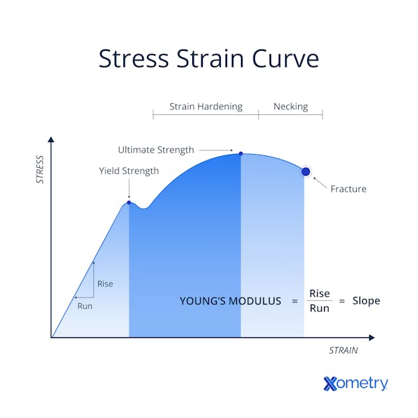
Stress-strain curve.
What Are the Characteristics of Fracture?
Fracture in materials describes the process of a material breakage under stress. When a fracture occurs, characteristic behaviors can be observed and analyzed. Listed below are some characteristics of fracture:
- Cleavage planes are smooth, flat, and often reflective surfaces along which the material cleaves or splits. These occur along crystal boundaries, which are planes of weakness in the material.
- Dimples are round depressions or irregularities on the fracture surface. They are characteristic of ductile materials and suggestive of plastic deformation and energy absorption, immediately prior to fracture.
- Shear lips are indicative of fracture resulting from micro-void coalescence. The surface of the fracture often looks fibrous or powdery.
- Hackles are chevron patterns seen on the fracture surface. They indicate (point towards) the direction of crack propagation and can help determine the mode of fracture.
What Are the Types of Fracture That Occur in a Material?
Fractures can occur in essentially three modes, characterized by a specific type of deformation and failure. These modes may result from tensile, compressive, shear, impact, cyclic, or complex mode loading. The types of fracture in a material are listed below:
- Ductile Fractures: Ductile fractures show significant plastic deformation before fracture. This behavior is characterized by extensive necking, dimples on the fracture surface, and gradual failure. Ductile fractures generally occur in metals and some polymers. In fact, the final failure mode is often essentially brittle, as the capacity for ductile behavior is exceeded.
- Brittle Fractures: Brittle fractures occur in materials that exhibit minimal (often no) plastic deformation prior to cleavage. The absence of necking, a flat or glossy fracture surface, and little energy absorption all indicate a brittle failure mode. Brittle fractures are typical of materials such as ceramics and glass, but several types of iron also exhibit generally brittle behaviors.
- Fatigue Fractures: Fatigue fractures occur due to repeated cyclic loading, triggering progressive crack growth or propagation. They typically exhibit a characteristic "beach-like" appearance with concentric markings known as beach marks.
The Fracture Strength of Ceramics and Inorganic Glasses
The fracture strength of ceramics and inorganic glass results directly from their atomic and crystalline structures. Ceramics are renowned for their high strength, stiffness, and inherent brittleness. Having a highly ordered crystalline structure results in very strong atomic bonds within the crystal lattice, providing for high strength. Wherever a crack or flaw is present in the material, stress concentration will act as a crack focus, and propagation along cleavage lines will be rapid. Ceramics also display little to no plastic deformation, which means that they cannot undergo plastic deformation to dissipate energy. This generally results in sudden and catastrophic failure once a critical stress level is reached.
Inorganic glass (window glass or silica glass), on the other hand, tends to be highly amorphous, i.e., has a disordered atomic structure. Their fracture mode differs from crystalline materials due to the absence of a well-defined crystalline lattice or cleavage planes. This group lacks grain boundaries and generally lacks crystal defects that can act as stress concentrators for crack initiation. The resulting uniform distribution of stress leads to higher fracture strength than typical polycrystalline ceramics. Like ceramics, inorganic glass has near-zero plastic deformation capability, suffering virtually no plastic deformation before fracture. However, these materials are generally highly sensitive to surface defects or microcracks, which act as stress concentrators, significantly affecting the fracture strength of the material.
What Is the Fracture Strength of Carbon Fiber?
The fracture strength of carbon fibers can vary depending on several factors, including: the type of carbon fiber (single-walled carbon nanotubes (SWCNT) or multiwalled carbon nanotubes (MWCNT)), manufacturing process, fiber orientation, and resin matrix used in composite materials. Typical carbon fibers have tensile strengths often exceeding 5 GPa (gigapascals) or 725,000 psi (pounds per square inch). The fracture strength of carbon fiber composites is considerably lower than that of the fibers. Fracture strengths for carbon fiber composites are typically reported as ranging from 200 MPa to 3 GPa and higher.
What Is the Fracture Strength of Aluminum?
The fracture strength of aluminum varies depending on various factors, such as: alloy composition, heat treatment, work-hardening, manufacturing process, and testing conditions. The fracture strength of commonly used aluminum alloys ranges from 100 MPa to 600 MPa, or approximately 14,500 psi to 87,000 psi. Much of this range is a direct result of process, rather than being fundamental to the alloy.
Aluminum alloys are often designed with a balance between strength and ductility, enabling them to often exhibit good toughness and the ability to undergo significant plastic deformation before fracture. This can result in lower consequences of failure, as structures survive greater abuse without total collapse. The strength (and other properties) of aluminum alloys can be further enhanced through various means such as: alloying elements, heat treatment, cold working, and precipitation hardening.
What Is Fracture Point in Fracture Strength?
The fracture point in any material test or product failure is the point in a loading cycle at which the part under load breaks. For ductile materials, the breakage is generally into two parts, and potentially into many parts for brittle materials.
How Does Corrosion Affect Fracture Strength?
Corrosion can be generally weakening as it reduces the amount of material available to carry a load. This mode is evident and obvious, as the part under load shows clear signs of erosive decay. However, a much more insidious and less obvious form is corrosion that occurs at microcracks. These cracks then deepen and extend, so the part suffers stress concentration that is not so evident on visual inspection. A final form of corrosion effect on the fracture strength of parts can occur when point corrosion or pitting provides another type of stress concentration. This is a particular feature of some stainless steel in marine environments.
How Does Temperature Affect Fracture Strength?
Temperature can have a significant impact on the fracture strength of some materials. This can result from changes in atomic/molecular mobility, thermal expansion, and microstructural transformations.
Ductile materials generally exhibit decreased fracture strength with increasing temperature. This can result from the decreased yield strength and increased ductility due to increased atomic/molecular mobility within the material, enabling higher dislocation rates under load. Another effect of temperature is diffusion-assisted cracking or environmental embrittlement. Elevated temperatures can accelerate diffusion processes, leading to increased susceptibility to environmental factors (such as oxidation or hydrogen embrittlement) that can degrade the material's fracture strength.
Brittle materials, on the other hand, often exhibit complex behavior under varying temperature conditions. Differences in coefficients of thermal expansion between a material and its environment (where the material is externally constrained or differentially heated) can result in thermal stress. Some brittle materials undergo phase transformations at specific temperature ranges. These transformations can introduce internal stresses, alter the material's microstructure, and affect fracture behavior. Rapid temperature changes can cause thermal shock, resulting in significant temperature gradients within the material. This can lead to localized stresses and thermal cracking, reducing the fracture strength.
Does Manufacturing Technique Impact Fracture Strength of Materials?
Many materials can be significantly altered by particular manufacturing techniques that influence their fracture strength. Medium- and high-carbon steels can be hot-quenched and tempered to hugely increase their fracture strength (among other properties). Inorganic glass materials, on the other hand, can generally be tempered after manufacture. The materials are held at a temperature close to the glass transition temperature allowing time for internal stresses to dissipate. This increases the impact fracture strength significantly. In most materials, some aspects of the manufacturing process can be adjusted (or processes added) to enhance the fracture strength, though this can be at the cost of degrading other properties.
What Is the Difference Between Fracture Strength and Tensile Strength?
Fracture strength and tensile strength are related but quite distinct material properties. Tensile strength measures a material's resistance to permanent distortion under tensile load. It represents the maximum stress a material can withstand before it fails to plastic deformation in tension. Fracture strength, on the other hand, quantifies the maximum stress a material can withstand before it fractures or breaks apart. Fracture strength can include resistance to failure under various loading conditions, including tensile, compressive, bending, or shear stress.
Tensile strength measures the maximum stress a material can withstand before deformation results, while fracture strength represents the maximum stress right at the point of material fracture.
Summary
Xometry provides a wide range of manufacturing capabilities and other value-added services for all of your prototyping and production needs. Visit our website to learn more or to request a free, no-obligation quote.
Disclaimer
The content appearing on this webpage is for informational purposes only. Xometry makes no representation or warranty of any kind, be it expressed or implied, as to the accuracy, completeness, or validity of the information. Any performance parameters, geometric tolerances, specific design features, quality and types of materials, or processes should not be inferred to represent what will be delivered by third-party suppliers or manufacturers through Xometry’s network. Buyers seeking quotes for parts are responsible for defining the specific requirements for those parts. Please refer to our terms and conditions for more information.