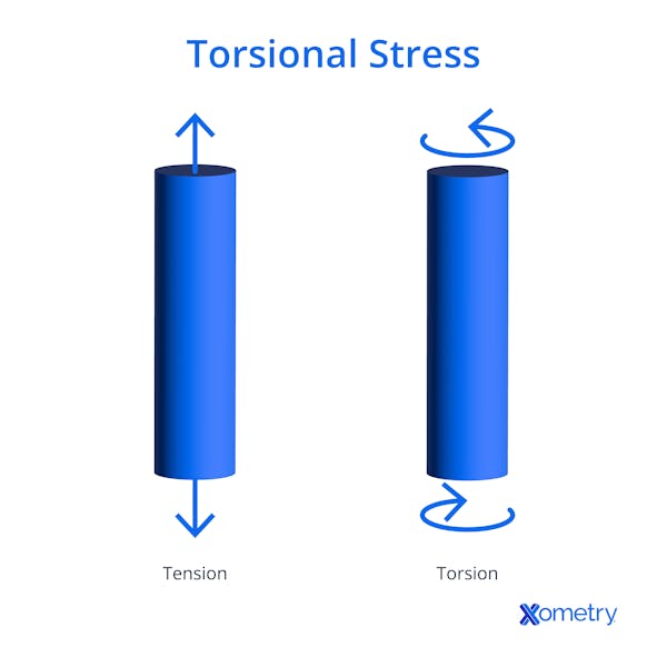
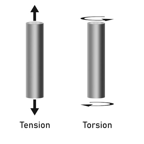
Torsional stress is one of four common loading mechanisms along with compression, tension, and shear. Torsional stress differs from these because the load is a torque load that is applied transversely rather than longitudinally.
This article will go into detail about what torsional stress is, how it works, and how it is calculated.
An Introduction to Torsional Stress
Torsional stress is a form of shear stress experienced by a body when a twisting force is applied. An example of torsional stress can be seen in a car’s axle. A car's engine/gearbox will attempt to turn the car’s axle, while the wheels on the other end of the axle will resist the turning. This will cause torsional stress about the center point of the axle.
It is important to understand the torsional physics applied to a load-bearing shaft, or body, to predict the shaft performance. Torsional stresses may cause elastic or plastic deformation to a shaft, and so shafts must be designed to properly resist torsional stresses.

How Torsional Stress Works
Torsional stress works in much the same way a bending moment works by applying a force at a distance along a lever arm. The only difference is that in a bending moment, the force is applied parallel to the axis. In torsional stress, the force is applied perpendicular to the axis of rotation. This results in a twisting force being exerted.
Torsional stress can be caused by a force couple acting about the center point of a shaft. A couple is two forces that act at the same distance from the point of rotation in an opposite and equal manner. Examples of a force couple causing torsional stress can be found in anything that rotates including car axles, gear shafts, drills, mandrels, and wind turbine generators. In all of these examples, torsional stress affects the object along the whole length of its axis.
One last thing to note is torsion does cause shear stress. This is because torsional stress is not applied uniformly between the acting point of the force and the point of rotation. Instead, the force applied starts at zero at the point of rotation and gradually increases along the radius to the acting point of the force.
Torsional Stress vs. Normal Stress
Normal stress, such as compression or tension, acts normally on the cross-section of an object. Torsional stress, however, works perpendicular to the cross-section about a center point. For compression and tension to occur, both forces must act concentrically. If the forces are not concentric a shear force will be induced—whereas torsional forces must only be parallel, opposite, and an equal distance away from the midpoint.
Torsional Stress Formula
The magnitude of the torsional stress depends on a few factors including the distance of the applied force from the center of rotation, the twisting moment, and the polar moment of inertia. These factors are all considered in the equation for torsional stress below:
t=Tr/J
Where:
t = Torsional stress
T = Transmitted torque
r = Distance from the center of rotation
J = Polar moment of inertia area
The radius is measured in meters and the units for torsional stress are given in newton meters or pascals (Pa).
To calculate the torsional stress, the torsional stress formula must be used. Firstly the value for the variables: the distance between the applied load and the center of rotation, the torque being transmitted, and the polar moment of inertia area must all be identified. Secondly, the values need to be substituted into the torsional stress equations. Then the formula will lead to a value for the torsional stress in pascals.
There are a few assumptions that are required to be true to allow the torsion equation to effectively analyze the torsional stress of an object. The assumptions are listed below:
- The material must be the same throughout the body.
- The load should be uniformly distributed along the shaft axis.
- The torque must not exceed the elastic deformation of the material.
- The shaft cross-section has to be circular.
- The length of the shaft must not change during loading.
Torsional Stress vs. Bending Stress
Both bending and torsional loads are moments, in which a force is applied at a distance along an arm. However, torsional stress is caused by a force that acts transversely about an axis of rotation; this causes the body to rotate. Conversely, a bending stress acts longitudinally to an axis which causes the body to bend along its axis.
Disclaimer
The content appearing on this webpage is for informational purposes only. Xometry makes no representation or warranty of any kind, be it expressed or implied, as to the accuracy, completeness, or validity of the information. Any performance parameters, geometric tolerances, specific design features, quality and types of materials, or processes should not be inferred to represent what will be delivered by third-party suppliers or manufacturers through Xometry’s network. Buyers seeking quotes for parts are responsible for defining the specific requirements for those parts. Please refer to our terms and conditions for more information.


