CNC plasma cutting is a hit in manufacturing because it can cut through metals, like aluminum, copper, and steel, in a fairly hands-off way, thanks to a computer guiding it. In this article, we’ll cover how it works, what it’s used for, and explain all its components.
What is CNC Plasma Cutting?
Computer numerical controlled (CNC) plasma cutting is a manufacturing process used to cut up to 30mm—and sometimes more—of many different materials that are electrically conductive. It’s faster than other methods, like oxy-fuel and thermal cutting, and is also repeatable (but less so with thin-gauge conductive materials). It can also be used in water to keep any heat-affected zones cool(er). The process is quite affordable and has brought the cost of cut parts down.
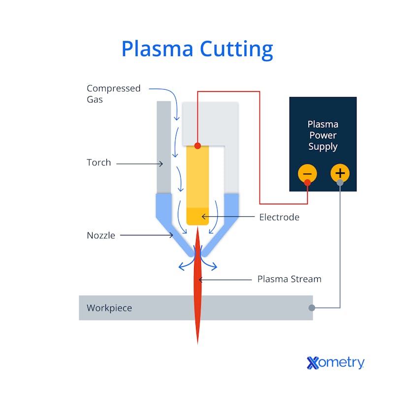
As a very brief description of how it works, the process involves uploading a design to the CNC plasma cutter machine using relevant software so that the cutter knows exactly where to go and where to cut. The diagram below illustrates the CNC plasma cutting process.
Components
Let’s have a look at each of the components shown in the above image (in clockwise order) to see what they are and what role they play in the process.
Compressed Gas
This is needed to push the plasma out of the machine through the nozzle so that it can smoothly cut through the metal.
Torch
Two types of torch are used in the process—a high-frequency spark system (HFSS) and a moving-contact start-pilot arc system (MCSP). To create the spark, a HFSS uses high-voltage electricity, and has a transformer, capacitors, and spark-gap assembly, while a MCSP system makes a small pilot arc from either a moving electrode or a moving nozzle. MCSPs can be used on sensitive electronics, but the same can’t be said of HFSSs that produce a little too much electrical noise.
Nozzle
This directs the plasma stream and controls the direction of the cuts, as well as their shape.
Workpiece
This has to be metal because of its electrical conductivity, but its hardness, thickness, and melting point all play an important role in how it’ll be cut. In addition to the materials mentioned in the intro, brass is another metal used in this method.
Plasma Stream
This is the cutting tool used and is essentially a super hot gas (over 20,000°C!) that comes out of the nozzle and blasted on the workpiece—this melts the metal and provides the cut. It’s sometimes called a high-velocity plasma jet.
Electrode
This part makes the electric spark that converts the compressed gas into plasma, kind of like an ignition switch on a gas range.
Power Supply
The power supply can affect what you can cut. For instance, 3mm steel can be cut with a 12A and 120V supply, but 20mm steel will likely need a 60A and 240V supply. Anything thicker than 30mm will probably need a three-phase plasma cutter. If you don’t use plasma cutting for heavy-duty applications you could always use inverter-based plasma cutters which are more energy-efficient.
Here are some more aspects of the process which aren’t pictured in the diagram, but are still important.
CNC System
Cutters with CNC technology provide accurate calculations, and are faster, easier to use, and more efficient than regular plasma cutters. There’s very little room for error, so cut-offs are kept way down.
CAD File
Computer-aided designs (CADs) are pretty much the blueprints for the cutting you’re about to do. When the design is complete, computer-aided manufacturing (CAM) software will convert that CAD file into a machine-readable code. This is essentially instructions for the machine on how to carry out the procedure and could be in DXF (drawing exchange format), which is made up of X, Y, and Z coordinates and plans out the path of the torch, or any other type that’s compatible with your CNC machine. This is a good thing to check before buying the software, and all the details will be in the product description.
CNC Program
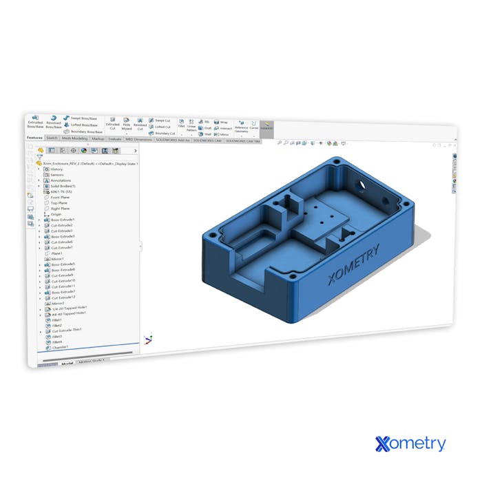
When the CAD file is ready, it’s uploaded to the CNC program which translates it into G-code—the language understood by CNC machines. The code instructions provided won’t only control the path, but also how fast the tool moves. Below you can see one of our CAD models.
Torch Movement Control
This is all controlled and predetermined in the G-code and it all depends on the shape you want to cut, the material, the plate thickness, and the duty cycle of the cutter (how long it can work before needing to cool down).
CNC Machine
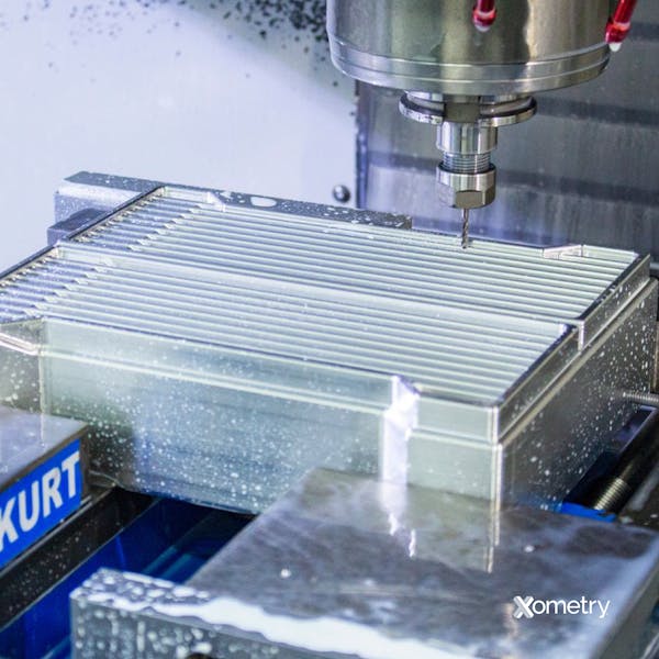
The CNC machine is what holds everything together. If it’s accuracy, consistency, and efficiency you’re after, you’ll want a CNC machine rather than do it manually. CNC machines are quite fast, reduce material wastage, and don’t really make any major mistakes. Inside this machine, you’ll find the cutting table, the plasma cutting torch, the computer, the workpiece, the cooling system, and the power supply. This is an image of one of our CNC machines at Xometry:
Cooling System
This is the system within the machine that helps keep things cool and the torch last longer. It uses a combination of conduction, radiation, and convection to move heat away from the torch, and is actually quite similar to cooling systems in cars, consisting of a torch, cooling lines, pump, radiator, coolant, and reservoir.
Cutting Table
The backbone of this entire system, the cutting table is what holds the workpiece in place, but also has everything else bolted to it.
Frequently Asked Questions
Here are a few of the common questions we get asked about CNC plasma cutting.
What’s the difference between CNC plasma and laser cutting?
Both laser and plasma cutting can seem quite similar, and aside from their main difference—plasma cutting uses high-velocity plasma flow and laser cutting uses high-concentration light energy—they have a few other dissimilarities. Laser cutting is usually more precise and accurate, and is compatible with both conductive and non-conductive materials, but plasma cutters have a lower initial capital outlay and are faster. The below picture shows a part made with laser cutting:

What’s the difference between CNC plasma and flame cutting?
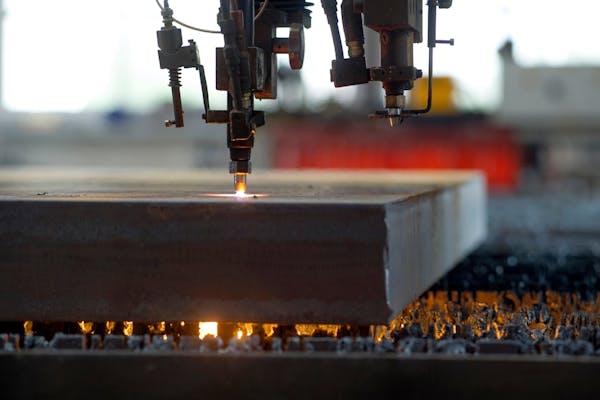
Flame cutting is a process that uses an oxy-fuel flame with a burst of oxygen to make cuts. It’s more basic and a lot less refined than CNC cutting and is better suited for materials over 25mm thick. It doesn’t cut as clean as plasma, but it’s better for portable fabrication tasks, and is often cheaper, too. Although both methods can be controlled with CNC systems, flame cutters (like the one pictured below) are not really designed for it. Plus, they can only cut ferrous metals.
Flame cutting thick-gauge steel.
Image Credit: Shutterstock.com/fotomarc
How much does CNC plasma cutting cost, comparatively?
This form of cutting is generally cheaper than other methods because the machines can be less expensive than laser or waterjet cutters, but this will understandably depend on the model you’re looking at—its power, capabilities, and any extra features. These cutters also have lower operating costs because they don’t need any consumables other than gas which isn’t too pricey. Although the maintenance cost of plasma cutters isn't exactly low, the method overall is considered cost-effective.
How Xometry Can Help
To learn more about CNC plasma cutting, or any other type of cutting, reach out to one of our Xometry representatives who would be happy to help. You can also choose from our wide range of manufacturing services, like CNC machining, 3D printing, and laser cutting. To get started, you can request a free no-obligation quote today.
Disclaimer
The content appearing on this webpage is for informational purposes only. Xometry makes no representation or warranty of any kind, be it expressed or implied, as to the accuracy, completeness, or validity of the information. Any performance parameters, geometric tolerances, specific design features, quality and types of materials, or processes should not be inferred to represent what will be delivered by third-party suppliers or manufacturers through Xometry’s network. Buyers seeking quotes for parts are responsible for defining the specific requirements for those parts. Please refer to our terms and conditions for more information.
