[Mini Guide] Design Tips for Sheet Cutting
Discover best practices and cost-saving design tips for your sheet cut parts in this mini guide.

Sheet cutting is a manufacturing process that involves slicing flat stock material along a defined profile to create a specific shape. It is typically performed using a high-powered CNC laser or waterjet. From one-off batches to mass production, Xometry's sheet cutting service allows custom designs to be cut in various materials, including plastics, elastomers, composites, metals, and more.
We've built a mini guide below that borrows some of the tips covered in our full sheet cutting design guide and highlights them below. These guidelines are meant to help you save on cost and ensure manufacturable designs. Let's get started!
Minimum Feature-to-Feature Distances for Laser and Waterjet Cutting
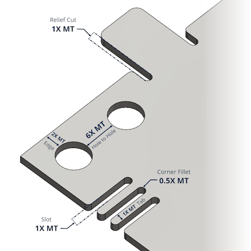
A minimum distance between features should be maintained to ensure the integrity of the cut.
The guidelines below will ensure reliable results, no matter the cutting method.
- Minimum Hole to Edge Distance = 2X MT or 0.125”, whichever is smaller
- Minimum Hole to Hole Distance = 6X MT or 0.125”, whichever is smaller
- Minimum Relief Cuts = 0.010” or 1X MT, whichever is greater
- Minimum Corner Fillets = 0.5X MT or 0.125”, whichever is smaller
- Minimum Tab Thickness = 0.063” or 1X MT, whichever is greater
- Minimum Slot Thickness = 0.040” or 1X MT, whichever is greater

Explode Your Text
When text is added to a design, it may be in an active state, meaning that although the text is visible on the screen, it may not actually be outlined for laser or waterjet cutting. Make sure to convert text to a shape with an outline or “explode” the text so it can be cut on the model.

It is also important to add joining or “stencil-like” bridges on free-floating text features like the holes in D, O, P, Q, or other closed-loop characters. Otherwise, the letters will just be a letter-shaped hole! The 3D viewer on Xometry's quoting page will show you what features are registered. Learn more about preparing your DXF files.
Notches and Slots
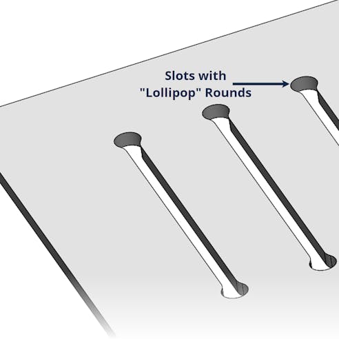
Notches and slots must be designed in the file, even if they are at the kerf thickness of the sheet cutting process. For example, a notch or slot of 0.040” should be designed to that width. It is recommended for slot features to have exaggerated “lollipop” rounds on at least one side to help compensate for the pierce hole, which will be larger than the cutting thickness (kerf).

Use Standard Gauges
Sheet cutting depends on stock material sizes to provide economical and quick-turn parts. Using common stock sizes or standard gauges for the material you are designing around is necessary to prevent delays in material sourcing.
If a design thickness is within the tolerance range of a standard gauge, Xometry will source that standard gauge for the project. Thickness tolerances are independent of cutting tolerances, as they rely on the raw stock material’s tolerance range.
Some processes, such as plasma cutting, flame cutting, and waterjet cutting, can slice through very thick stock material but may require a manual quote review. Typically, the thicker the stock, the less likely a large sheet size is available.

Looking for More Design Guidelines and Tips?


