STEP and STL are two of the most popular file formats used in 3D design and manufacturing. While similar, they’re not interchangeable; one is used for detailed and precise information for more complex parts, while the other is just a simple format that holds only the very basic data. Read on to find out which is which, why they’re both needed in additive manufacturing and how to make this conversion.
What is STEP?
STEP is the acronym for Standard for the Exchange of Product Model Data, and it’s the most common and reliable cross-compatible data transfer tool between CAD and CAM (computer-aided design and computer-assisted manufacturing, respectively) systems. A STEP file can represent the full 3D design data and store all the details of the mechanical design, kinematics, and process planning, as well as metadata for a part or assembly. It works by providing 3D model construction data and metadata in an ASCII format defined by the STEP standard reference, ISO 10303-242:2014, and you’ll see it as “.STP” at the end of the file name. Many service providers like to use these files when providing quotes or offering advice, but clearly, it’s much more than a mere communication method.
What is STL?
STL (stereolithography/standard triangle language/standard tessellation language) is considered the standard file type for 3D printers in the mid-to-low price range. It was originally developed by 3D Systems when they first started making 3D printers and is also an ASCII format file. It works by splitting designs into lots of small triangles, with each one being defined by three points (x, y, z coordinates) that outline its shape. STL is a little on the older side and is known for being somewhat limited, mainly because it doesn’t contain any color or texture information and has a slightly more disjointed file structure. It does work well, however, for many tasks. It also contains information that tells the printer which side of the triangle should be facing outward. Here’s an example of an STL file:
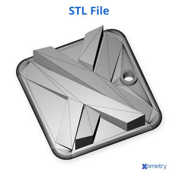
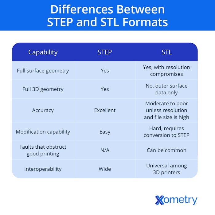
The following table will help you understand the key differences between these two file types.
For more in-depth information on each file type, take a look at our dedicated articles:
Before You Get Started
Generally, we recommend not converting your STEP files to STL for manufacturing. STEP files inherently contain more useful data, such as units and solid data. From a manufacturing side, we can use STEP files to create high-resolution mesh files for printing to ensure the highest print quality. STEP files are also typically required for subtractive manufacturing processes like CNC machining.
At Xometry, your STEP file will cover all your bases, including 3D printing, machining, sheet cutting, and more. So, if you're planning on using our services, there may be no need to convert your files at all! If you want to proceed anyway, then continue with the steps outlined in the sections below.
1. Open the STEP file
Once you’ve located the STEP file you want on your computer, right-click on it, and select “open with” to choose the CAD program. This will load up the file. There is another way to do this though the CAD software. Open the program, find the file, drag and drop it in, or load it up from within the program.
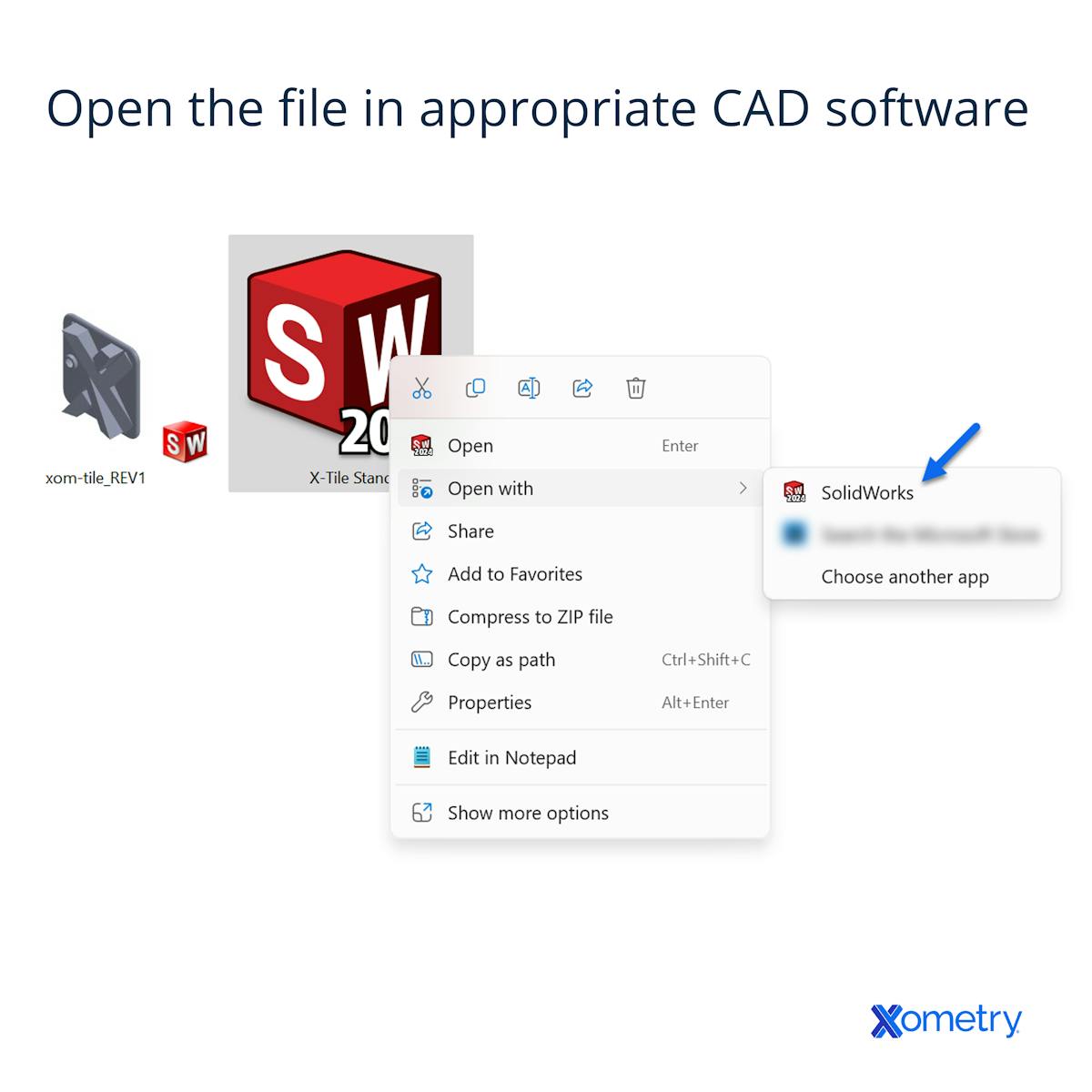
2. Open the file export settings
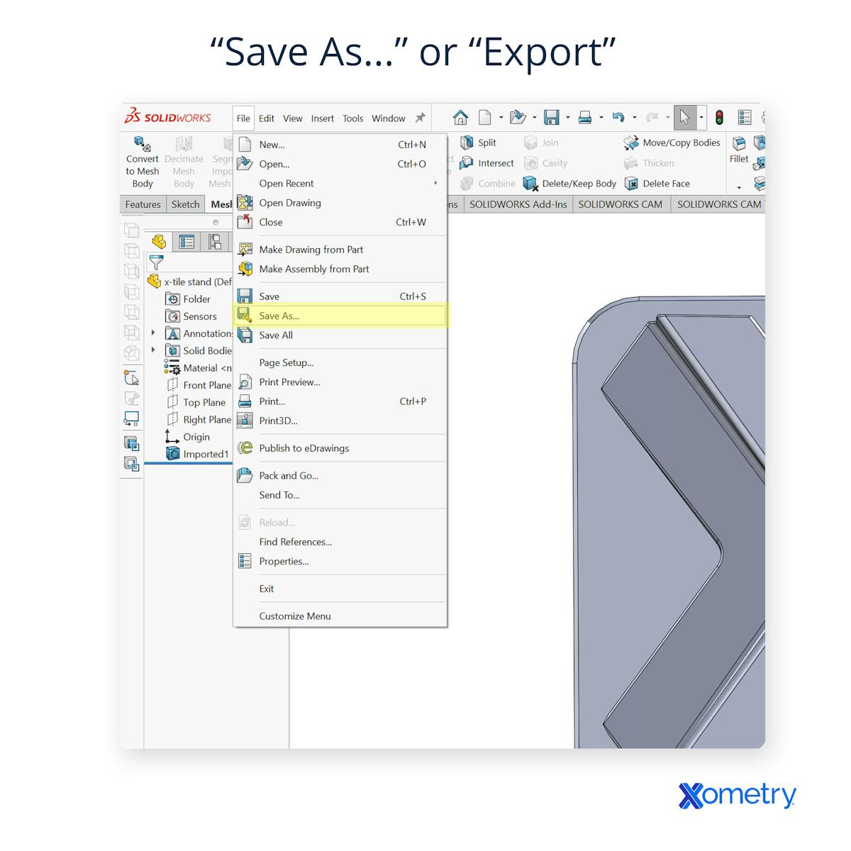
When your model is in the program, head over to the export options, which are usually under the File menu. This will typically be either “Save As…” or “Export.” No matter what you do, don’t just save the file under the standard “Save” option because that will just export it as it is.
4. Check for and configure STL export options
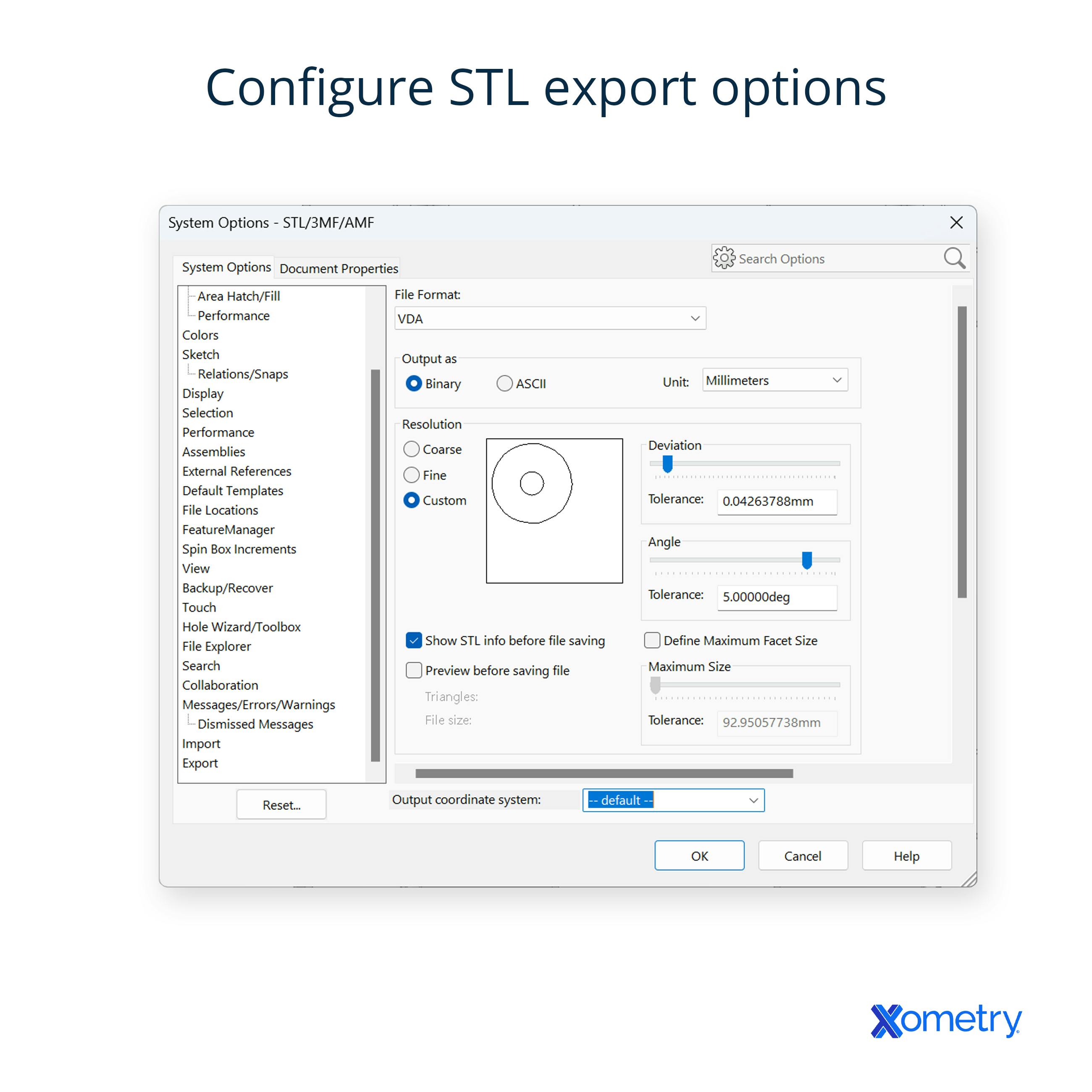
When you’ve clicked on the STL option, you’ll most likely be greeted with a box that allows you to check the export options. In SOLIDWORKS, for instance, clicking on “Options” will open an additional box for configuring the file. Whichever options you’re given, check them closely because they will affect your final file.
5. Save the file
Once you’re happy with the settings, go ahead and export your new STL file. It’s as simple as that. You can check to see how the conversion went by opening the new file in a 3D viewer or by uploading it to the Xometry Instant Quoting Engine® and using our online viewer to check it. That way, you can get a quote for any of our 3D printing processes.

Frequently Asked Questions on STEP and STL
What programs can open STEP files?
There are lots of programs that do this, and they’ll usually allow you to convert the file, too. Some typical examples are STP viewers and CAD packages like SOLIDWORKS, Catia, Creo (formerly ProE), AutoDesk Fusion, Siemens NX (formerly UniGraphics), and many others. There’s also FreeCAD (which is also a converter), Tinkercad, LibreCAD, SketchUp, and Onshape—a lightweight cloud-based CAD package that stores your design and print files in a public directory in the cloud if you’re using the free version. There’s also a paid version which is more secure, and a Xometry add-in for it.
What’s the best converter?
There are plenty of good options to choose from to convert STEP to STL. We’ve already mentioned Onshape and FreeCAD—a powerful program that can handle lots of different formats and has some awesome analysis, modification, and repair tools and features. Another option is GOM Inspect which offers various function levels.
Are there any conversion problems to know about?
There are some, yes. For instance, you might lose detail or experience inaccurate scaling or incorrect resolution settings. Also, low-quality CAD models can actually cause the STL file to have some gaps, non-manifold edges, or mesh errors. If that happens, you’ll need to fix the problem before 3D printing.
How Xometry Can Help
If you need any clarification on the conversion or to learn more about the different file formats used in custom 3D printing services, please feel free to reach out to one of our representatives. At Xometry we actually accept many different native file formats, including STEP and STL! This makes it easy to upload your CAD files for instant quotes without going through conversions. In fact, we actually prefer users upload STEP files whenever possible as they can be used for quoting and manufacturing both additive processes like 3D printing, and subtractive processes like CNC machining. If you're looking for custom-made parts, you can get an instant quote by uploading your native files to the Xometry Instant Quoting Engine® and get started straight away.
Summary
Disclaimer
The content appearing on this webpage is for informational purposes only. Xometry makes no representation or warranty of any kind, be it expressed or implied, as to the accuracy, completeness, or validity of the information. Any performance parameters, geometric tolerances, specific design features, quality and types of materials, or processes should not be inferred to represent what will be delivered by third-party suppliers or manufacturers through Xometry’s network. Buyers seeking quotes for parts are responsible for defining the specific requirements for those parts. Please refer to our terms and conditions for more information.


